Continental L-Head Overhaul Manual - Igor Chudov
Continental L-Head Overhaul Manual - Igor Chudov
Continental L-Head Overhaul Manual - Igor Chudov

Create successful ePaper yourself
Turn your PDF publications into a flip-book with our unique Google optimized e-Paper software.
Page 60 CONTINENTAL L-HEAD ENGINE MANUAL<br />
Pistons are cam and taper ground, and this must<br />
be taken into consideration when checking alignment<br />
of the assembly, since the diameter in line<br />
with the piston pin would be less at the top of the<br />
skirt than at the bottom.<br />
Figure 134--Checking connecting rod assembly<br />
for alignment<br />
PISTON RINGS<br />
Check the piston rings in the cylinders for gap.<br />
To do this, insert a piston in the cylinder bore<br />
in an inverted position and then insert each ring<br />
one at a time about 2" down in the bore and bring<br />
the bottom edge of the piston up against the ring<br />
to square it up in the cylinder bore.<br />
Check the gap between the ends of the ring with<br />
a feeler gauge in accordance with specificatie, ns<br />
shown in the Limits and Clearance chart.<br />
RECOMMENDED METHOD OF INSTALLING<br />
PISTON RINGS<br />
1. Grip the connecting rod in a vise with lead<br />
lined jaws to hold the piston firmly and roll each<br />
of the straight side rings in its groove to be sure<br />
there are no burrs or other interference with the<br />
free action of the ring in the groove.<br />
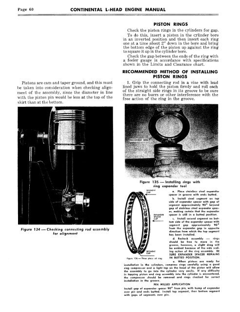
Figure 135- Installing rings with<br />
ring expander tool<br />
SEGMENT<br />
a~<br />
~<br />
a. Place stainless steel expander<br />
spacer in groove with ends butted.<br />
b. Install steel segment on top<br />
~<br />
side of expander spacer with gap of<br />
segment approximately 90 ° ~<br />
beyond<br />
gap of stainless steel expander spacer,<br />
making certain that the expander<br />
spacer is still in a butted position.<br />
c. Install second segment on botlom<br />
side of the expander spacer with<br />
segment<br />
°<br />
gap approximately 90<br />
from the expander gap in opposite<br />
direction from which the top segment<br />
has been installed.<br />
d. Recheck assembly ~ rings<br />
should be free to move in the<br />
groove, however, a slight drag will<br />
~<br />
be evident because of the side scaling<br />
action of the ring assembly. BE<br />
SURE EXPANDER SPACER REMAINS<br />
Figure 136--Three piece oil ring IN BUTTED POSITION.<br />
e. When pistons are ready for<br />
installation in the cylinders, compress rings carefully using a good<br />
ring compressor and a light tap on the head of the piston will allow<br />
the assembly to go into the cylinder very easily. If any difficulty<br />
in tapping piston and ring assembly into the cylinder is encountered,<br />
the compressor should be removed and rings checked for correct<br />
installation in the groove.<br />
PIN MILLED APPLICATION<br />
Install gap of expander spacer 90 ° from pin, with hump of expander<br />
over pin and ends butted. Install top segment, then bottom segment<br />
with gaps of segments over pin.