Continental L-Head Overhaul Manual - Igor Chudov
Continental L-Head Overhaul Manual - Igor Chudov
Continental L-Head Overhaul Manual - Igor Chudov

Create successful ePaper yourself
Turn your PDF publications into a flip-book with our unique Google optimized e-Paper software.
Page 49~ CONTINENTAL L-HEAD ENGINE MANUAL<br />
the weights (6) causes them to swing outward on their<br />
pivots -- this energy is opposed by the governor spring<br />
(7). The tension of this spring is the means of setting the<br />
governor to act at a predetermined speed.<br />
When the engine is not running, the governor spring<br />
holds the throttle valve wide open.<br />
Wken the engine is started, the weights swing out,<br />
moving the thrust sleeve (14) along the driveshaft. This<br />
movement is transmitted through the thrust bearing (8)<br />
to the rocker yoke (9) on the throttle lever shaft. This<br />
movement, in turn, moves the governor control lever (13)<br />
toward the dosed throttle position. The weights continue<br />
to move out until the weight force and spring force are in<br />
balance -- when the throttle will be in position to maintain<br />
the governed R.P.M.<br />
Adj ustment<br />
1 -- The speed of the Governor is regulated by adjusting<br />
screw (15).<br />
2 -- S~nsitivity of the governor can be regulated, by<br />
auxiliary adjusting screw (12). Surging or hunting<br />
under load conditions can usually be eliminated by<br />
broadening the regulation with this adjusting screw.<br />
3 -- No Load Surge -- is eliminated by means of the<br />
bumper screw (11) at no load-open throttle position.<br />
CAM GEAR GOVERNOR<br />
Some L-head engines use the <strong>Continental</strong> designed "builtin"<br />
cam gear driven governor. Sealed, dust proof and<br />
engine lubricated, it is compact and easily adjusted. The<br />
control shaft floats on two needle bearings to remove<br />
friction for closer, more accurate control through the<br />
whole power range.<br />
|<br />
Figure 91 Cam Gear Governor<br />
This governor is a variahle speed type and has no speed<br />
adjustment other than amount of travel the control rod<br />
is moved. Control rod movement is determined by accelerator<br />
pedal or hand control linkages. Idle surge adjusting<br />
screw should be adjusted in just enough to eliminate<br />
any tendency of engine to surge.<br />
TAILSHAFT GOVERNORS<br />
Many industrial applications with torque converter drives<br />
want to maintain a constant output shaft speed under<br />
varying load conditions. This requires the governor to be<br />
driven by the output shaft where it can sense output shaft<br />
speed variations rather than engine speed.<br />
Taitshaft governors are of the long range type which<br />
provide regulation over a wide range of speeds and can<br />
be set up to maintain any desired speed in that range.<br />
The tailshaft governor is mounted on the torque converter<br />
and is gear-driven. This type governor has two<br />
operating levers one of which is the throttle lever to<br />
set the desired output shaft speed and the other lever is<br />
connected directly to and operates the carburetor throttle<br />
control lever by a mechanical linkage. This linkage, preferably<br />
should be a short, straight rod with ball joints at<br />
each end or if the linkage is Ionia" walled tubing should<br />
be used so that weight and friction of the linkage is<br />
reduced to an absolute minimum.<br />
The torque converter governor, being’ driven by the output<br />
shaft, senses only output shaft speed and controls the<br />
engine throttle accordingly. It is therefore very important<br />
that the engine be protected, with an overspeed device<br />
which will sense engine speed and limit that speed to a<br />
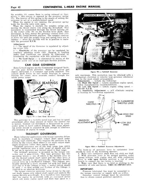
Figure 92 -- Tailshaft Governor<br />
safe maximum. This protection may be obtained wi’th a<br />
mechanical, electrical or velocity type governor whic’hever<br />
may be the most siraple arrangement.<br />
Adjustments -- include the following:<br />
(A) High Idle Speed -- Limits maximum engine speed,<br />
follow manufacturers recommendations.<br />
(B) Low Idle Speed -- Limits engine idling speed --<br />
400-600 R.P.M.<br />
(C) Sensitivity Adjustment -- will eliminate surging<br />
or hunting bv hrondonin~ regulation.<br />
Figure 92A--Tailshaft Governor Adjustments<br />
The hook-up of governor lever to carburetor lever<br />
should be done in the following manner:<br />
1. Make sure carburetor shaft does not stick nor bind.<br />
2. With governor lever in its normal position under<br />
spring tension, xvith engine shut off, with carburetor<br />
lever in wide open throttle position, a rod of exact<br />
length to connect the two levers is inserted.<br />
3. Make sure l~hat there is no bind or sticking in the<br />
assembly of rods and levers. THIS IS IMPORTANT.<br />
IMPORTANT:<br />
Pressure lubricated line must be connected to<br />
the torque converter or supply with an orifice.<br />
Governor control linkage must be absolutely<br />
free to obtain correct governor operation.