Continental L-Head Overhaul Manual - Igor Chudov
Continental L-Head Overhaul Manual - Igor Chudov
Continental L-Head Overhaul Manual - Igor Chudov

Create successful ePaper yourself
Turn your PDF publications into a flip-book with our unique Google optimized e-Paper software.
When the correct fit is obtained you must be able<br />
to withdraw the feeler with a pull of 5-10 pounds<br />
on the scale, with the feeler inserted between the<br />
piston and the cylinder midway between the piston<br />
pin bosses where the diameter of the piston is the<br />
greatest. Check the fit of the piston when it is approximately<br />
2" down in the cylinder bore in an inverted<br />
position.<br />
PISTON PINS<br />
necting rod for wear. If worn and you are using the<br />
original pistons witl~ a service set of rings, an oversize<br />
piston pin may be obtained in .003 or .005"<br />
oversize.<br />
The piston pin hole in the piston and the bushing<br />
in the connecting rod may be honed to increase<br />
Figure 131 ~. Pressing in Piston Pin Bushing<br />
their diameter to obtain the desired fit as shown in<br />
,our Limits and Clearance Chart.<br />
Note that while the chart specifies a<br />
light push fit of the pin in the piston, there<br />
is a definite clearance of the piston pin in the<br />
connecting rod.<br />
CONNECTING ROD<br />
Replace the bushing in the connecting rod if new<br />
pistons and sleeves are used. Using an arbor press,<br />
press out the old bushing and press in the new one<br />
-- after which the bushing must be honed to obtain<br />
the correct fit of the pin in the bushing as shown<br />
on Limits and Clearance Chart.<br />
If there is an excess of stock in the piston pin<br />
bushing, it may be reamed first, then honed. In any<br />
event, the final operation should be done with a<br />
hone to obtain the desired fit with better than 75%<br />
bearing area on the pin.<br />
CONTINENTAL L-HEAD ENGINE MANUAL Page 59<br />
PISTON AND CONNECTING<br />
ROD ASSEMBLY<br />
1. Assemble the pistons on the connecting rod<br />
by first heating them in some form of oven or in<br />
hot water to a minimum temperature of 160°F.<br />
When heated, the piston pin will enter the piston<br />
very easily and can be tapped through the connecting<br />
rod and into place without distorting the piston.<br />
The snap rings must be assembled in the grooves,<br />
making sure they are fully seated in place.<br />
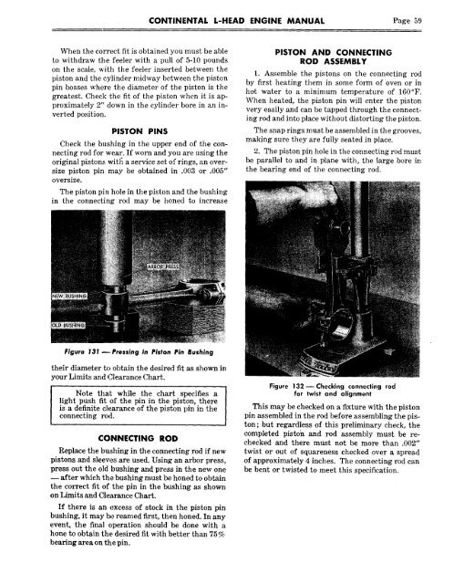
2. The piston pin hole in the connecting rod must<br />
be parallel to and in plane with, the large bore in<br />
the bearing end of the connecting rod.<br />
Figure 132 m Checking connecting rod<br />
for twist and alignment<br />
This may be checked on a fixture with the piston<br />
pin assembled in the rod before assembling the piston;<br />
but regardless of this preliminary check, the<br />
completed pistoh and rod assembly must be rechecked<br />
and there must not be more than .002"<br />
twist or out of squareness checked over a spread<br />
of approximately 4 inches. The connecting rod can<br />
be bent or twisted to meet this specification.