Xilinx UG230 Spartan-3E FPGA Starter Kit Board User Guide
Xilinx UG230 Spartan-3E FPGA Starter Kit Board User Guide
Xilinx UG230 Spartan-3E FPGA Starter Kit Board User Guide

Create successful ePaper yourself
Turn your PDF publications into a flip-book with our unique Google optimized e-Paper software.
Chapter 7: RS-232 Serial Ports<br />
UCF Location Constraints<br />
Figure 7-1 shows the connection between the <strong>FPGA</strong> and the two DB9 connectors. The<br />
<strong>FPGA</strong> supplies serial output data using LVTTL or LVCMOS levels to the Maxim device,<br />
which in turn, converts the logic value to the appropriate RS-232 voltage level. Likewise,<br />
the Maxim device converts the RS-232 serial input data to LVTTL levels for the <strong>FPGA</strong>. A<br />
series resistor between the Maxim output pin and the <strong>FPGA</strong>’s RXD pin protects against<br />
accidental logic conflicts.<br />
Hardware flow control is not supported on the connector. The port’s DCD, DTR, and DSR<br />
signals connect together, as shown in Figure 7-1. Similarly, the port’s RTS and CTS signals<br />
connect together.<br />
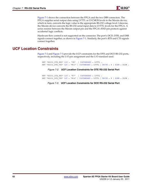
Figure 7-2 and Figure 7-3 provide the UCF constraints for the DTE and DCE RS-232 ports,<br />
respectively, including the I/O pin assignment and the I/O standard used.<br />
NET "RS232_DTE_RXD" LOC = "U8" | IOSTANDARD = LVTTL ;<br />
NET "RS232_DTE_TXD" LOC = "M13" | IOSTANDARD = LVTTL | DRIVE = 8 | SLEW = SLOW ;<br />
Figure 7-2: UCF Location Constraints for DTE RS-232 Serial Port<br />
NET "RS232_DCE_RXD" LOC = "R7" | IOSTANDARD = LVTTL ;<br />
NET "RS232_DCE_TXD" LOC = "M14" | IOSTANDARD = LVTTL | DRIVE = 8 | SLEW = SLOW ;<br />
Figure 7-3: UCF Location Constraints for DCE RS-232 Serial Port<br />
62 www.xilinx.com <strong>Spartan</strong>-<strong>3E</strong> <strong>FPGA</strong> <strong>Starter</strong> <strong>Kit</strong> <strong>Board</strong> <strong>User</strong> <strong>Guide</strong><br />
<strong>UG230</strong> (v1.2) January 20, 2011<br />
R