PTOLEMY II - CiteSeerX
PTOLEMY II - CiteSeerX
PTOLEMY II - CiteSeerX

You also want an ePaper? Increase the reach of your titles
YUMPU automatically turns print PDFs into web optimized ePapers that Google loves.
Using Vergil<br />
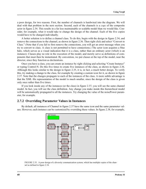
a poor design, for two reasons. First, the number of channels is hardwired into the diagram. We will<br />
deal with that problem in the next section. Second, each of the channels is a copy of the composite<br />
actor in figure 2.34. This results in a far less maintainable or scalable model than we would like. Consider,<br />
for example, what it would take to change the design of the channel. Each of the five copies<br />
would have to be changed individually.<br />
A better solution is to define a channel class. To do this, begin with the design in figure 2.34, and<br />
remove the connections to the channel, as shown in figure 2.36. Then right click and select “Convert to<br />
Class.” (Note that if you fail to first remove the connections, you will get an error message when you<br />
try to convert to class. A class is not permitted to have connections.) The actor icon acquires a blue<br />
halo, which serves as a visual indication that it is a class, rather than an ordinary actor (which is an<br />
instance). Classes play no role in the execution of the model, and merely serve as definitions of components<br />
that must then be instantiated. By convention, we put classes at the top of the model, near the<br />
director, since they function as declarations.<br />
Once you have a class, you can create an instance by right clicking and selecting “Create Instance”<br />
or typing Control-N. Do this five times to create five instances of the class, as shown in figure 2.36.<br />
Although this looks similar to the design in figure 2.35, it is, in fact, a much better design. To verify<br />
this, try making a change to the class, for example by creating a custom icon for it, as shown in figure<br />
2.37. Note that the changes propagate to each of the instances of the class. A more subtle advantage is<br />
that the XML file representation of the model is much smaller, since the design of the class is given<br />
only once rather than five times.<br />
If you look inside any of the instances (or the class) in figure 2.37, you will see the same channel<br />
model. In fact, you will see the class definition. Any change you make inside this hierarchical model<br />
will be automatically propagated to all the instances. Try changing the value of the noisePower parameter,<br />
for example.<br />
2.7.2 Overriding Parameter Values in Instances<br />
By default, all instances of Channel in figure 2.37 have the same icon and the same parameter values.<br />
However, each instance can be customized by overriding these values. In figure 2.38, for example,<br />
FIGURE 2.35. A poor design of a diversity communication system, which has multiple copies of the channel<br />
as defined in figure 2.34.<br />
68 Ptolemy <strong>II</strong>