warning - Whirlpool
warning - Whirlpool
warning - Whirlpool

You also want an ePaper? Increase the reach of your titles
YUMPU automatically turns print PDFs into web optimized ePapers that Google loves.
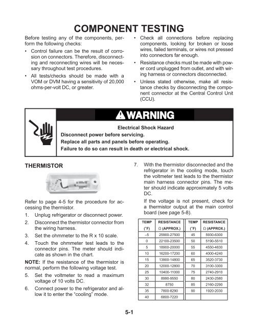
THERMISTOR<br />
COMPONENT TESTING<br />
Before testing any of the components, perform<br />
the following checks:<br />
• Control failure can be the result of corrosion<br />
on connectors. Therefore, disconnecting<br />
and reconnecting wires will be necessary<br />
throughout test procedures.<br />
• All tests/checks should be made with a<br />
VOM or DVM having a sensitivity of 20,000<br />
ohms-per-volt DC, or greater.<br />
WARNING<br />
Electrical Shock Hazard<br />
Disconnect power before servicing.<br />
Replace all parts and panels before operating.<br />
Failure to do so can result in death or electrical shock.<br />
Refer to page 4-5 for the procedure for accessing<br />
the thermistor.<br />
1. Unplug refrigerator or disconnect power.<br />
2. Disconnect the thermistor connector from<br />
the wiring harness.<br />
3. Set the ohmmeter to the R x 10 scale.<br />
4. Touch the ohmmeter test leads to the<br />
connector pins. The meter should indicate<br />
as shown in the chart.<br />
NOTE: If the resistance of the thermistor is<br />
normal, perform the following voltage test.<br />
5. Set the voltmeter to read a maximum<br />
voltage of 10 volts DC.<br />
6. Connect power to the refrigerator and allow<br />
it to enter the “cooling” mode.<br />
5-1<br />
•<br />
•<br />
•<br />
Check all connections before replacing<br />
components, looking for broken or loose<br />
wires, failed terminals, or wires not pressed<br />
into connectors far enough.<br />
Resistance checks must be made with power<br />
cord unplugged from outlet, and with wiring<br />
harness or connectors disconnected.<br />
Unless stated otherwise, make all resistance<br />
checks by disconnecting the component<br />
connector at the Central Control Unit<br />
(CCU).<br />
7. With the thermistor disconnected and the<br />
refrigerator in the cooling mode, touch<br />
the voltmeter test leads to the thermistor<br />
main harness connector pins. The meter<br />
should indicate approximately 5 volts<br />
DC.<br />
If the voltage is not present, check for<br />
a thermistor output at the main control<br />
board (see page 5-8).<br />
TEMP RESISTANCE TEMP RESISTANCE<br />
(°F) Ω (APPROX.) (°F) Ω (APPROX.)<br />
–5 25900-27500 45 5930-6300<br />
0 22100-23500 50 5190-5510<br />
5 18900-20000 55 4550-4830<br />
10 16200-17200 60 4000-4240<br />
15 13900-14800 65 3520-3730<br />
20 12000-12800 70 3100-3300<br />
25 10400-11000 75 2740-2910<br />
30 8990-9550 80 2430-2580<br />
32 8750 85 2160-2290<br />
35 7800-8290 90 1920-2030<br />
40 6800-7220