warning - Whirlpool
warning - Whirlpool
warning - Whirlpool

You also want an ePaper? Increase the reach of your titles
YUMPU automatically turns print PDFs into web optimized ePapers that Google loves.
WARNING<br />
Electrical Shock Hazard<br />
Disconnect power before servicing.<br />
Replace all parts and panels before operating.<br />
Failure to do so can result in death or electrical shock.<br />
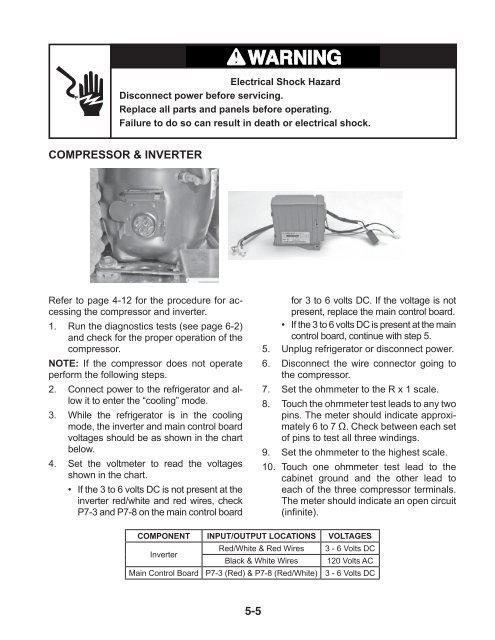
COMPRESSOR & INVERTER<br />
Refer to page 4-12 for the procedure for accessing<br />
the compressor and inverter.<br />
1. Run the diagnostics tests (see page 6-2)<br />
and check for the proper operation of the<br />
compressor.<br />
NOTE: If the compressor does not operate<br />
perform the following steps.<br />
2. Connect power to the refrigerator and allow<br />
it to enter the “cooling” mode.<br />
3. While the refrigerator is in the cooling<br />
mode, the inverter and main control board<br />
voltages should be as shown in the chart<br />
below.<br />
4. Set the voltmeter to read the voltages<br />
shown in the chart.<br />
• If the 3 to 6 volts DC is not present at the<br />
inverter red/white and red wires, check<br />
P7-3 and P7-8 on the main control board<br />
5-5<br />
for 3 to 6 volts DC. If the voltage is not<br />
present, replace the main control board.<br />
• If the 3 to 6 volts DC is present at the main<br />
control board, continue with step 5.<br />
5. Unplug refrigerator or disconnect power.<br />
6. Disconnect the wire connector going to<br />
the compressor.<br />
7. Set the ohmmeter to the R x 1 scale.<br />
8. Touch the ohmmeter test leads to any two<br />
pins. The meter should indicate approximately<br />
6 to 7 Ω. Check between each set<br />
of pins to test all three windings.<br />
9. Set the ohmmeter to the highest scale.<br />
10. Touch one ohmmeter test lead to the<br />
cabinet ground and the other lead to<br />
each of the three compressor terminals.<br />
The meter should indicate an open circuit<br />
(infinite).<br />
COMPONENT INPUT/OUTPUT LOCATIONS VOLTAGES<br />
Inverter<br />
Red/White & Red Wires<br />
Black & White Wires<br />
3 - 6 Volts DC<br />
120 Volts AC<br />
Main Control Board P7-3 (Red) & P7-8 (Red/White) 3 - 6 Volts DC