warning - Whirlpool
warning - Whirlpool
warning - Whirlpool

Create successful ePaper yourself
Turn your PDF publications into a flip-book with our unique Google optimized e-Paper software.
MAIN CONTROL BOARD<br />
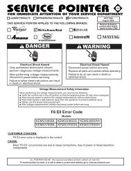
WARNING<br />
Electrical Shock Hazard<br />
Disconnect power before servicing.<br />
Replace all parts and panels before operating.<br />
Failure to do so can result in death or electrical shock.<br />
Refer to page 4-12 for the procedure for accessing the main control board.<br />
NOTE: See the chart for the main control board test specifications.<br />
P5<br />
P8<br />
3 2<br />
1<br />
1<br />
P4<br />
1<br />
1<br />
P7<br />
P3<br />
1<br />
1<br />
P6<br />
5-8<br />
PLUG PIN # DESCRIPTION OUTPUT CONDITION<br />
P2<br />
P3<br />
P4<br />
P5<br />
P6<br />
P7<br />
1 Communication Line N/A<br />
2 Display Voltage 12 VDC Measured at pins 2 & 3<br />
3 GND GND<br />
1 Ref. Thermistor GND<br />
2 Frz. Thermistor GND<br />
3 Ref. Thermistor Output 5 VDC Measured at pins 1 & 3<br />
4 Frz. Thermistor Output 5 VDC Measured at pins 2 & 4<br />
1 Ref. Door Sw Enable 120 VAC<br />
2 Frz. Door Sw Enable 120 VAC<br />
3 N/A<br />
4 Ref. Door Input 120 VAC Voltage present when door is open<br />
5 Ice Maker Valve Input 120 VAC Voltage present when ice maker is energized<br />
6 Dispenser Valve Input 120 VAC Voltage present when dispenser valve is energized<br />
7 Bimetal Input 120 VAC Voltage present when bimetal is closed<br />
8 Frz. Door Input 120 VAC<br />
1 AC GND AC GND<br />
2 AC L1 120 VAC<br />
3 AC Neutral AC Neutral<br />
4 AC Neutral AC Neutral<br />
5 AC L1 120 VAC<br />
1 Condenser Fan 120 VAC Voltage present when condenser fan is on<br />
2 N/A<br />
3 N/A<br />
4 Defrost Heater 120 VAC Voltage present when defrost heater is on<br />
5 Ice Maker Enable 120 VAC<br />
1 Air Door<br />
2 Air Door<br />
3 Compressor Drive 3 - 6 VDC Measured at pins 3 & 8<br />
4 Evap. Fan Feedback N/A<br />
5 Evap. Fan Constant 12 VDC Measured at pins 5 & 9<br />
6 Air Door<br />
7 Air Door<br />
8 Compressor Drive 3 - 6 VDC Measured at pins 3 & 8<br />
9 Evap. Fan Ground Evap. GND<br />
Voltage present when I/M bail arm is down & I/M<br />
is active<br />
10 Evap. Fan Run Voltage 5 - 12 VDC Measured at pins 9 & 10