

1747-6.22, Backup Scanner User Manual
1747-6.22, Backup Scanner User Manual
1747-6.22, Backup Scanner User Manual

You also want an ePaper? Increase the reach of your titles
YUMPU automatically turns print PDFs into web optimized ePapers that Google loves.
1-22 Overview<br />
How the <strong>Scanner</strong><br />
Interacts with<br />
Adapters<br />
SLC Local Chassis<br />
Publication <strong>1747</strong>-<strong>6.22</strong><br />
Processor <strong>Scanner</strong><br />
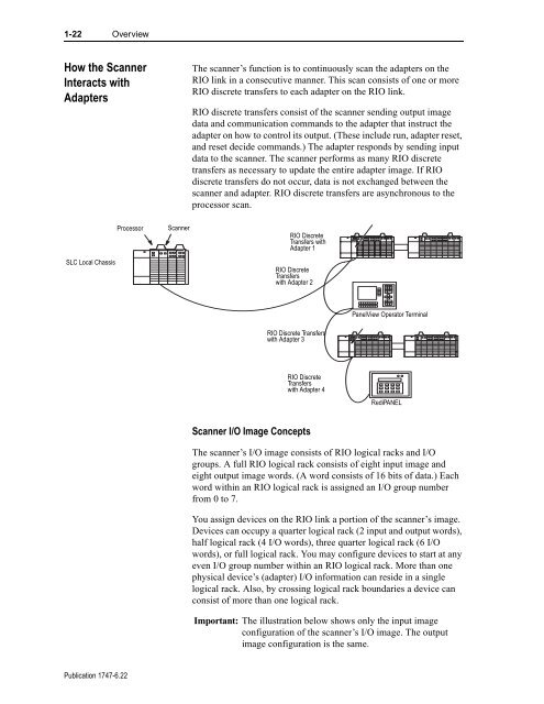
The scanner’s function is to continuously scan the adapters on the<br />
RIO link in a consecutive manner. This scan consists of one or more<br />
RIO discrete transfers to each adapter on the RIO link.<br />
RIO discrete transfers consist of the scanner sending output image<br />
data and communication commands to the adapter that instruct the<br />
adapter on how to control its output. (These include run, adapter reset,<br />
and reset decide commands.) The adapter responds by sending input<br />
data to the scanner. The scanner performs as many RIO discrete<br />
transfers as necessary to update the entire adapter image. If RIO<br />
discrete transfers do not occur, data is not exchanged between the<br />
scanner and adapter. RIO discrete transfers are asynchronous to the<br />
processor scan.<br />
RIO Discrete<br />
Transfers with<br />
Adapter 1<br />
RIO Discrete<br />
Transfers<br />
with Adapter 2<br />
RIO Discrete Transfers<br />
with Adapter 3<br />
RIO Discrete<br />
Transfers<br />
with Adapter 4<br />
<strong>Scanner</strong> I/O Image Concepts<br />
PanelView Operator Terminal<br />
RediPANEL<br />
The scanner’s I/O image consists of RIO logical racks and I/O<br />
groups. A full RIO logical rack consists of eight input image and<br />
eight output image words. (A word consists of 16 bits of data.) Each<br />
word within an RIO logical rack is assigned an I/O group number<br />
from 0 to 7.<br />
You assign devices on the RIO link a portion of the scanner’s image.<br />
Devices can occupy a quarter logical rack (2 input and output words),<br />
half logical rack (4 I/O words), three quarter logical rack (6 I/O<br />
words), or full logical rack. You may configure devices to start at any<br />
even I/O group number within an RIO logical rack. More than one<br />
physical device’s (adapter) I/O information can reside in a single<br />
logical rack. Also, by crossing logical rack boundaries a device can<br />
consist of more than one logical rack.<br />
Important: The illustration below shows only the input image<br />
configuration of the scanner’s I/O image. The output<br />
image configuration is the same.


