

1747-6.22, Backup Scanner User Manual
1747-6.22, Backup Scanner User Manual
1747-6.22, Backup Scanner User Manual

Create successful ePaper yourself
Turn your PDF publications into a flip-book with our unique Google optimized e-Paper software.
M0 File - RIO Device<br />
Reset Control<br />
Logical Rack 0 Device Inhibit Word 16<br />
Logical Rack 1Device Inhibit Word 17<br />
Logical Rack 2 Device Inhibit Word 18<br />
Logical Rack 3 Device Inhibit Word 19<br />
G File<br />
Device Address, Word 1<br />
MO (Control) File<br />
Bit Number (decimal)<br />
Logical Rack 0 Device Inhibit Word 16<br />
Logical Rack 1Device Inhibit Word 17<br />
Logical Rack 2 Device Inhibit Word 18<br />
Logical Rack 3 Device Inhibit Word 19<br />
<strong>Scanner</strong> Configuration and Programming 5-73<br />
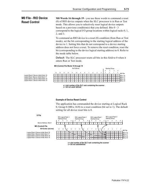
M0 Words 16 through 19 - you use these words to command a reset<br />
(0) of RIO device outputs when the SLC processor is in Run or Test<br />
mode. This allows you to selectively reset logical device outputs<br />
based on a previous condition(s) that you defined. Bits 0 - 3<br />
correspond to the logical I/O group locations within logical racks 0, 1,<br />
2, and 3.<br />
To command an RIO device to a reset (0) condition (from Run or Test<br />
mode), set the bit corresponding to the starting logical address of the<br />
device to 1. Setting bits that do not correspond to a device starting<br />
address does not force a reset. To remove the reset condition, reset the<br />
bit (corresponding to the device logical starting address) to 0. Refer to<br />
the mode table below.<br />
Default: The SLC processor resets all bits in this field to 0 when it<br />
enters Run or Test mode.<br />
MO (Control) File Words 16 through 19<br />
Not Defined Starting Group<br />
15<br />
x<br />
x<br />
x<br />
x<br />
14<br />
x<br />
x<br />
x<br />
x<br />
13<br />
x<br />
x<br />
x<br />
x<br />
12<br />
x<br />
x<br />
x<br />
x<br />
11<br />
x<br />
x<br />
x<br />
x<br />
10<br />
x<br />
x<br />
x<br />
x<br />
9<br />
x<br />
x<br />
x<br />
x<br />
e = slot number of the SLC rack containing the scanner<br />
x = bit not used/ defined<br />
8<br />
x<br />
x<br />
x<br />
7<br />
x<br />
x<br />
x<br />
Example of Device Reset Control<br />
The application has commanded the device starting at Logical Rack<br />
0, Group 0 (M0:e.16/0) to a reset condition (bit set to 1). The default<br />
setting for all device reset bits is 0.<br />
RIO Logical Rack 3<br />
Starting Group<br />
6 4 2<br />
0<br />
15<br />
x<br />
x<br />
x<br />
x<br />
0<br />
14<br />
x<br />
x<br />
x<br />
x<br />
1<br />
13<br />
x<br />
x<br />
x<br />
x<br />
0<br />
0<br />
12<br />
x<br />
x<br />
x<br />
x<br />
x<br />
RIO Logical Rack 2<br />
Starting Group<br />
6 4 2 0<br />
0<br />
11<br />
x<br />
x<br />
x<br />
x<br />
0<br />
10<br />
x<br />
x<br />
x<br />
x<br />
1<br />
9<br />
x<br />
x<br />
x<br />
x<br />
0<br />
8<br />
x<br />
x<br />
x<br />
x<br />
x<br />
x<br />
x<br />
x<br />
x<br />
6<br />
x<br />
x<br />
x<br />
x<br />
x<br />
x<br />
x<br />
x<br />
5<br />
x<br />
x<br />
x<br />
x<br />
x<br />
x<br />
x<br />
x<br />
4<br />
x<br />
x<br />
x<br />
x<br />
RIO Logical Rack 1<br />
Starting Group<br />
6 4 2<br />
e = slot number of the SLC rack containing the scanner<br />
x = bit not used/defined<br />
0<br />
7<br />
0<br />
6<br />
0<br />
5<br />
0<br />
1<br />
4<br />
x<br />
x<br />
x<br />
x<br />
6<br />
3<br />
0<br />
0<br />
0<br />
0<br />
6<br />
3<br />
0<br />
0<br />
0<br />
0<br />
4<br />
2<br />
0<br />
0<br />
0<br />
0<br />
4<br />
2<br />
0<br />
0<br />
0<br />
0<br />
1<br />
2<br />
0<br />
0<br />
0<br />
0<br />
RIO Logical Rack 0<br />
Starting Group<br />
2<br />
1<br />
0<br />
0<br />
0<br />
0<br />
0<br />
0<br />
0<br />
0<br />
0<br />
0<br />
1 0 0 1<br />
M0 File<br />
M0:e.16<br />
M0:e.17<br />
M0:e.18<br />
M0:e.19<br />
0<br />
0<br />
1<br />
0<br />
0<br />
0<br />
M0 File<br />
M0:e.16<br />
M0:e.17<br />
M0:e.18<br />
M0:e.19<br />
Publication <strong>1747</strong>-<strong>6.22</strong>


