

1747-6.22, Backup Scanner User Manual
1747-6.22, Backup Scanner User Manual
1747-6.22, Backup Scanner User Manual

Create successful ePaper yourself
Turn your PDF publications into a flip-book with our unique Google optimized e-Paper software.
1-32 Overview<br />
Logical<br />
Rack 0<br />
Word 0<br />
Word 1<br />
Word 2<br />
Word 3<br />
Word 4<br />
Word 5<br />
Word 6<br />
Word 7<br />
Publication <strong>1747</strong>-<strong>6.22</strong><br />
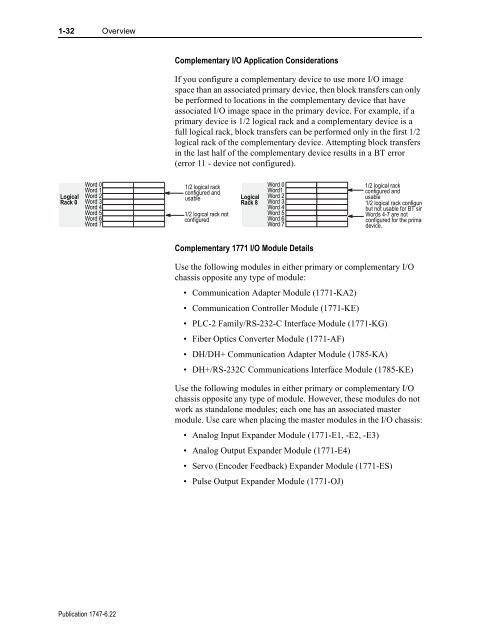
Complementary I/O Application Considerations<br />
If you configure a complementary device to use more I/O image<br />
space than an associated primary device, then block transfers can only<br />
be performed to locations in the complementary device that have<br />
associated I/O image space in the primary device. For example, if a<br />
primary device is 1/2 logical rack and a complementary device is a<br />
full logical rack, block transfers can be performed only in the first 1/2<br />
logical rack of the complementary device. Attempting block transfers<br />
in the last half of the complementary device results in a BT error<br />
(error 11 - device not configured).<br />
1/2 logical rack<br />
configured and<br />
usable<br />
1/2 logical rack not<br />
configured<br />
Logical<br />
Rack 8<br />
Word 0<br />
Word1<br />
Word 2<br />
Word 3<br />
Word 4<br />
Word 5<br />
Word 6<br />
Word 7<br />
Complementary 1771 I/O Module Details<br />
1/2 logical rack<br />
configured and<br />
usable<br />
1/2 logical rack configure<br />
but not usable for BT sin<br />
Words 4-7 are not<br />
configured for the primar<br />
device.<br />
Use the following modules in either primary or complementary I/O<br />
chassis opposite any type of module:<br />
• Communication Adapter Module (1771-KA2)<br />
• Communication Controller Module (1771-KE)<br />
• PLC-2 Family/RS-232-C Interface Module (1771-KG)<br />
• Fiber Optics Converter Module (1771-AF)<br />
• DH/DH+ Communication Adapter Module (1785-KA)<br />
• DH+/RS-232C Communications Interface Module (1785-KE)<br />
Use the following modules in either primary or complementary I/O<br />
chassis opposite any type of module. However, these modules do not<br />
work as standalone modules; each one has an associated master<br />
module. Use care when placing the master modules in the I/O chassis:<br />
• Analog Input Expander Module (1771-E1, -E2, -E3)<br />
• Analog Output Expander Module (1771-E4)<br />
• Servo (Encoder Feedback) Expander Module (1771-ES)<br />
• Pulse Output Expander Module (1771-OJ)


