Embedded Systems Design with the Atmel AVR Microcontroller Part II
Embedded Systems Design with the Atmel AVR Microcontroller Part II
Embedded Systems Design with the Atmel AVR Microcontroller Part II

Create successful ePaper yourself
Turn your PDF publications into a flip-book with our unique Google optimized e-Paper software.
to PD4<br />
470<br />
200<br />
7.6. DC MOTOR SPEED AND DIRECTION CONTROL 221<br />
ZTX451<br />
ZTX551<br />
+<br />
12 VDC<br />
M<br />
-<br />
ZTX451<br />
ZTX551<br />
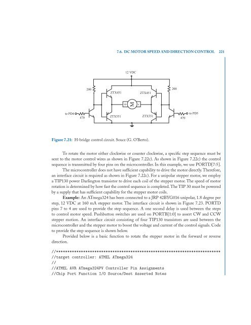
Figure 7.21: H-bridge control circuit. Souce (G. O’Berto).<br />
200<br />
470<br />
to PD5<br />
To rotate <strong>the</strong> motor ei<strong>the</strong>r clockwise or counter clockwise, a specific step sequence must be<br />
sent to <strong>the</strong> motor control wires as shown in Figure 7.22c). As shown in Figure 7.22c) <strong>the</strong> control<br />
sequence is transmitted by four pins on <strong>the</strong> microcontroller. In this example, we use PORTD[7:5].<br />
The microcontroller does not have sufficient capability to drive <strong>the</strong> motor directly. Therefore,<br />
an interface circuit is required as shown in Figure 7.22c). For a unipolar stepper motor, we employ<br />
a TIP130 power Darlington transistor to drive each coil of <strong>the</strong> stepper motor. The speed of motor<br />
rotation is determined by how fast <strong>the</strong> control sequence is completed. The TIP 30 must be powered<br />
by a supply that has sufficient capability for <strong>the</strong> stepper motor coils.<br />
Example: An ATmega324 has been connected to a JRP 42BYG016 unipolar, 1.8 degree per<br />
step, 12 VDC at 160 mA stepper motor. The interface circuit is shown in Figure 7.23. PORTD<br />
pins 7 to 4 are used to provide <strong>the</strong> step sequence. A one second delay is used between <strong>the</strong> steps<br />
to control motor speed. Pushbutton switches are used on PORTB[1:0] to assert CW and CCW<br />
stepper motion. An interface circuit consisting of four TIP130 transistors are used between <strong>the</strong><br />
microcontroller and <strong>the</strong> stepper motor to boost <strong>the</strong> voltage and current of <strong>the</strong> control signals. Code<br />
to provide <strong>the</strong> step sequence is shown below.<br />
Provided below is a basic function to rotate <strong>the</strong> stepper motor in <strong>the</strong> forward or reverse<br />
direction.<br />
//*************************************************************************<br />
//target controller: ATMEL ATmega324<br />
//<br />
//ATMEL <strong>AVR</strong> ATmega324PV Controller Pin Assignments<br />
//Chip Port Function I/O Source/Dest Asserted Notes