Embedded Systems Design with the Atmel AVR Microcontroller Part II
Embedded Systems Design with the Atmel AVR Microcontroller Part II
Embedded Systems Design with the Atmel AVR Microcontroller Part II

Create successful ePaper yourself
Turn your PDF publications into a flip-book with our unique Google optimized e-Paper software.
142 CHAPTER 6. TIMING SUBSYSTEM<br />
6.4.1 INPUT CAPTURE—MEASURING EXTERNAL TIMING EVENT<br />
In many applications, we are interested in measuring <strong>the</strong> elapsed time or <strong>the</strong> frequency of an external<br />
event using a microcontroller. Using <strong>the</strong> hardware and functional units discussed in <strong>the</strong> previous<br />
sections, we now present a procedure to accomplish <strong>the</strong> task of computing <strong>the</strong> frequency of an<br />
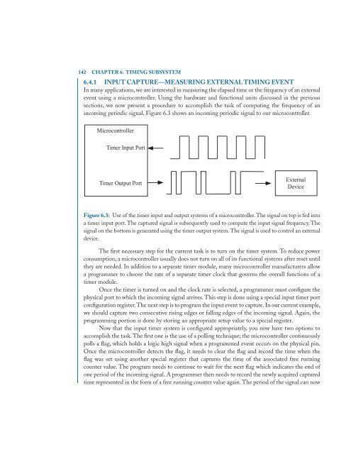
incoming periodic signal. Figure 6.3 shows an incoming periodic signal to our microcontroller.<br />
<strong>Microcontroller</strong><br />
Timer Input Port<br />
Timer Output Port<br />
External<br />
Device<br />
Figure 6.3: Use of <strong>the</strong> timer input and output systems of a microcontroller. The signal on top is fed into<br />
a timer input port. The captured signal is subsequently used to compute <strong>the</strong> input signal frequency. The<br />
signal on <strong>the</strong> bottom is generated using <strong>the</strong> timer output system. The signal is used to control an external<br />
device.<br />
The first necessary step for <strong>the</strong> current task is to turn on <strong>the</strong> timer system. To reduce power<br />
consumption, a microcontroller usually does not turn on all of its functional systems after reset until<br />
<strong>the</strong>y are needed. In addition to a separate timer module, many microcontroller manufacturers allow<br />
a programmer to choose <strong>the</strong> rate of a separate timer clock that governs <strong>the</strong> overall functions of a<br />
timer module.<br />
Once <strong>the</strong> timer is turned on and <strong>the</strong> clock rate is selected, a programmer must configure <strong>the</strong><br />
physical port to which <strong>the</strong> incoming signal arrives. This step is done using a special input timer port<br />
configuration register.The next step is to program <strong>the</strong> input event to capture. In our current example,<br />
we should capture two consecutive rising edges or falling edges of <strong>the</strong> incoming signal. Again, <strong>the</strong><br />
programming portion is done by storing an appropriate setup value to a special register.<br />
Now that <strong>the</strong> input timer system is configured appropriately, you now have two options to<br />
accomplish <strong>the</strong> task. The first one is <strong>the</strong> use of a polling technique; <strong>the</strong> microcontroller continuously<br />
polls a flag, which holds a logic high signal when a programmed event occurs on <strong>the</strong> physical pin.<br />
Once <strong>the</strong> microcontroller detects <strong>the</strong> flag, it needs to clear <strong>the</strong> flag and record <strong>the</strong> time when <strong>the</strong><br />
flag was set using ano<strong>the</strong>r special register that captures <strong>the</strong> time of <strong>the</strong> associated free running<br />
counter value. The program needs to continue to wait for <strong>the</strong> next flag which indicates <strong>the</strong> end of<br />
one period of <strong>the</strong> incoming signal. A programmer <strong>the</strong>n needs to record <strong>the</strong> newly acquired captured<br />
time represented in <strong>the</strong> form of a free running counter value again. The period of <strong>the</strong> signal can now