Embedded Systems Design with the Atmel AVR Microcontroller Part II
Embedded Systems Design with the Atmel AVR Microcontroller Part II
Embedded Systems Design with the Atmel AVR Microcontroller Part II

You also want an ePaper? Increase the reach of your titles
YUMPU automatically turns print PDFs into web optimized ePapers that Google loves.
USART<br />
Initialize<br />
USART<br />
data<br />
for TX<br />
USART<br />
Transmit<br />
ADC<br />
Initialize<br />
ch for<br />
conv<br />
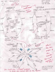
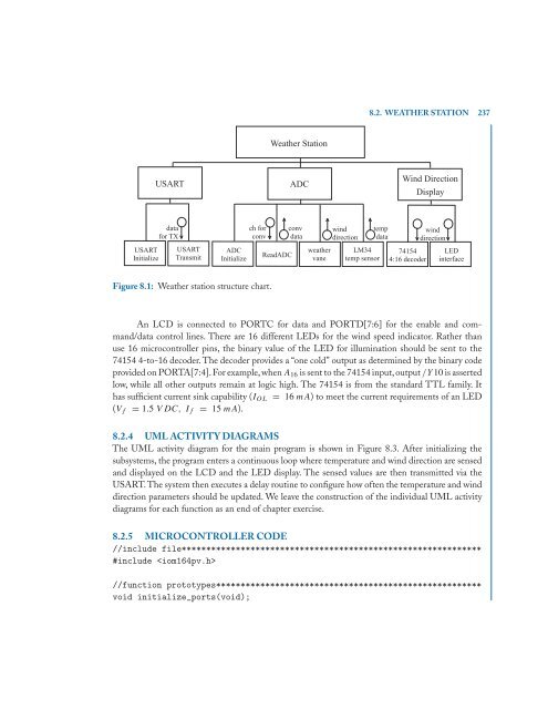
Figure 8.1: Wea<strong>the</strong>r station structure chart.<br />
Wea<strong>the</strong>r Station<br />
ReadADC<br />
ADC<br />
conv<br />
data<br />
wea<strong>the</strong>r<br />
vane<br />
wind<br />
direction<br />
LM34<br />
temp sensor<br />
8.2. WEATHER STATION 237<br />
temp<br />
data<br />
Wind Direction<br />
Display<br />
74154<br />
4:16 decoder<br />
wind<br />
direction<br />
LED<br />
interface<br />
An LCD is connected to PORTC for data and PORTD[7:6] for <strong>the</strong> enable and command/data<br />
control lines. There are 16 different LEDs for <strong>the</strong> wind speed indicator. Ra<strong>the</strong>r than<br />
use 16 microcontroller pins, <strong>the</strong> binary value of <strong>the</strong> LED for illumination should be sent to <strong>the</strong><br />
74154 4-to-16 decoder. The decoder provides a “one cold” output as determined by <strong>the</strong> binary code<br />
provided on PORTA[7:4]. For example, when A16 is sent to <strong>the</strong> 74154 input, output /Y10 is asserted<br />
low, while all o<strong>the</strong>r outputs remain at logic high. The 74154 is from <strong>the</strong> standard TTL family. It<br />
has sufficient current sink capability (IOL = 16 mA) to meet <strong>the</strong> current requirements of an LED<br />
(Vf = 1.5 VDC, If = 15 mA).<br />
8.2.4 UML ACTIVITY DIAGRAMS<br />
The UML activity diagram for <strong>the</strong> main program is shown in Figure 8.3. After initializing <strong>the</strong><br />
subsystems, <strong>the</strong> program enters a continuous loop where temperature and wind direction are sensed<br />
and displayed on <strong>the</strong> LCD and <strong>the</strong> LED display. The sensed values are <strong>the</strong>n transmitted via <strong>the</strong><br />
USART.The system <strong>the</strong>n executes a delay routine to configure how often <strong>the</strong> temperature and wind<br />
direction parameters should be updated. We leave <strong>the</strong> construction of <strong>the</strong> individual UML activity<br />
diagrams for each function as an end of chapter exercise.<br />
8.2.5 MICROCONTROLLER CODE<br />
//include file*************************************************************<br />
#include <br />
//function prototypes******************************************************<br />
void initialize_ports(void);