Embedded Systems Design with the Atmel AVR Microcontroller Part II
Embedded Systems Design with the Atmel AVR Microcontroller Part II
Embedded Systems Design with the Atmel AVR Microcontroller Part II

You also want an ePaper? Increase the reach of your titles
YUMPU automatically turns print PDFs into web optimized ePapers that Google loves.
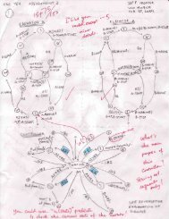
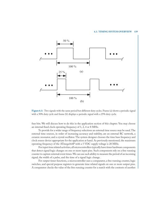
25 %<br />
50 %<br />
100 %<br />
100 %<br />
(a)<br />
(b)<br />
6.3. TIMING SYSTEM OVERVIEW 139<br />
Figure 6.1: Two signals <strong>with</strong> <strong>the</strong> same period but different duty cycles. Frame (a) shows a periodic signal<br />
<strong>with</strong> a 50% duty cycle and frame (b) displays a periodic signal <strong>with</strong> a 25% duty cycle.<br />
fuse bits. We will discuss how to do this in <strong>the</strong> application section of this chapter. You may choose<br />
an internal fixed clock operating frequency of 1, 2, 4 or 8 MHz.<br />
To provide for a wider range of frequency selections an external time source may be used. The<br />
external time sources, in order of increasing accuracy and stability, are an external RC network, a<br />
ceramic resonator, and a crystal oscillator. The system designer chooses <strong>the</strong> time base frequency and<br />
clock source device appropriate for <strong>the</strong> application at hand. As previously mentioned, <strong>the</strong> maximum<br />
operating frequency of <strong>the</strong> ATmega164P <strong>with</strong> a 5 VDC supply voltage is 20 MHz.<br />
For input time related activities,all microcontrollers typically have timer hardware components<br />
that detect signal logic changes on one or more input pins. Such components rely on a free running<br />
counter to capture external event times.We can use such ability to measure <strong>the</strong> period of an incoming<br />
signal, <strong>the</strong> width of a pulse, and <strong>the</strong> time of a signal logic change.<br />
For output timer functions, a microcontroller uses a comparator, a free running counter, logic<br />
switches, and special purpose registers to generate time related signals on one or more output pins.<br />
A comparator checks <strong>the</strong> value of <strong>the</strong> free running counter for a match <strong>with</strong> <strong>the</strong> contents of ano<strong>the</strong>r