Embedded Systems Design with the Atmel AVR Microcontroller Part II
Embedded Systems Design with the Atmel AVR Microcontroller Part II
Embedded Systems Design with the Atmel AVR Microcontroller Part II

Create successful ePaper yourself
Turn your PDF publications into a flip-book with our unique Google optimized e-Paper software.
Timer/Counter Control Register B (TCCR2B)<br />
7<br />
Timer/Counter Control Register A (TCCR2A)<br />
6.9. PROGRAMMING THE TIMER SYSTEM 159<br />
CS2[2:0] Clock Source<br />
000 None<br />
001 clkI/0 010 clkI/0 /8<br />
011 clkI/0 /32<br />
100 clkI/0 /64<br />
101 clkI/0 /128<br />
110 clkI/0 /256<br />
111 clkI/0 /1024<br />
Clock Select<br />
FOC2A FOC2B --- --- WGM22 CS22 CS21 CS20<br />
COM2A1 COM2A0 COM2B1 COM2B0 --- --- WGM21 WGM20<br />
Mode WGM[02:00]<br />
Waveform Generation<br />
Mode<br />
Mode<br />
0 000 Normal<br />
1 001 PWM, Phase Correct<br />
2 010 CTC<br />
3 011 Fast PWM<br />
4 100 Reserved<br />
5 101 PWM, Phase Correct<br />
6 110 Reserved<br />
7 111 Fast PWM<br />
Compare Output Mode, non-PWM Mode<br />
COM2A[1:0]<br />
00<br />
01<br />
10<br />
11<br />
COM2A[1:0]<br />
00<br />
01<br />
10<br />
11<br />
Description<br />
Normal, OC2A disconnected<br />
Toggle OC2A on compare match<br />
Clear OC2A on compare match<br />
Set OC2A on compare match<br />
Compare Output Mode, Fast PWM Mode<br />
COM2A[1:0]<br />
00<br />
01<br />
10<br />
11<br />
Description<br />
Normal, OC2A disconnected<br />
WGM22 = 0: normal operation,<br />
OC2A disconnected<br />
WGM22 = 1: Toggle OC2A on<br />
compare match<br />
Clear OC2A on compare match,<br />
set OC2A at Bottom<br />
(non-inverting mode)<br />
Set OC2A on compare match,<br />
clear OC2A at Bottom<br />
(inverting mode)<br />
Compare Output Mode, Phase Correct PWM<br />
Description<br />
Normal, OC2A disconnected<br />
WGM22 = 0: normal operation,<br />
OC2A disconnected<br />
WGM22 = 1: Toggle OC2A on<br />
compare match<br />
Clear OC2A on compare match,<br />
when upcounting. Set OC2A on<br />
compare match when down counting<br />
Set OC2A on compare match,<br />
when upcounting. Set OC2A on<br />
compare match when down counting<br />
Compare Output Mode, non-PWM Mode<br />
COM2B[1:0]<br />
00<br />
01<br />
10<br />
11<br />
COM2B[1:0]<br />
00<br />
01<br />
10<br />
11<br />
Description<br />
Normal, OC2B disconnected<br />
Toggle OC2B on compare match<br />
Clear OC2B on compare match<br />
Set OC2B on compare match<br />
Compare Output Mode, Fast PWM Mode<br />
COM2B[1:0]<br />
00<br />
01<br />
10<br />
11<br />
Description<br />
Normal, OC2B disconnected<br />
Reserved<br />
Clear OC2B on compare match,<br />
set OC2B at Bottom<br />
(non-inverting mode)<br />
Set OC2B on compare match,<br />
clear OC2B at Bottom<br />
(inverting mode)<br />
Compare Output Mode, Phase Correct PWM<br />
Description<br />
Normal, OC2B disconnected<br />
Reserved<br />
0<br />
Clear OC2B on compare match,<br />
when upcounting. Set OC2B on<br />
compare match when down counting<br />
Set OC2B on compare match,<br />
when upcounting. Set OC2B on<br />
compare match when down counting<br />
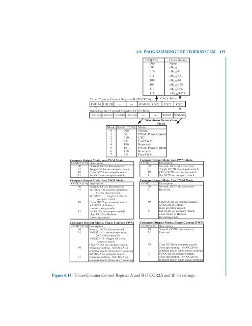
Figure 6.15: Timer/Counter Control Register A and B (TCCR2A and B) bit settings.