Embedded Systems Design with the Atmel AVR Microcontroller Part II
Embedded Systems Design with the Atmel AVR Microcontroller Part II
Embedded Systems Design with the Atmel AVR Microcontroller Part II

Create successful ePaper yourself
Turn your PDF publications into a flip-book with our unique Google optimized e-Paper software.
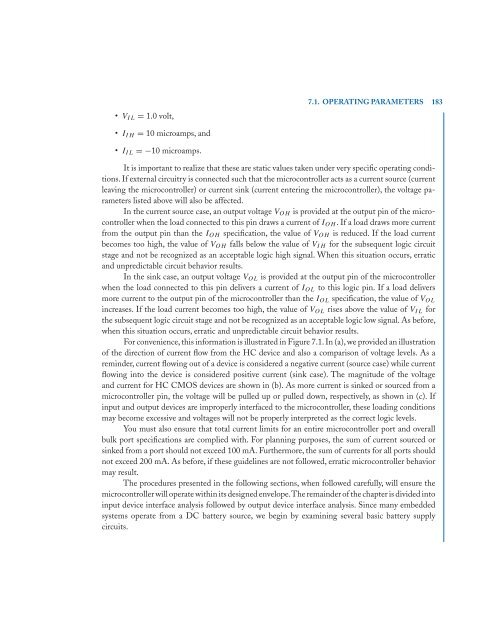
VIL = 1.0 volt,<br />
<strong>II</strong>H = 10 microamps, and<br />
<strong>II</strong>L =−10 microamps.<br />
7.1. OPERATING PARAMETERS 183<br />
It is important to realize that <strong>the</strong>se are static values taken under very specific operating conditions.<br />
If external circuitry is connected such that <strong>the</strong> microcontroller acts as a current source (current<br />
leaving <strong>the</strong> microcontroller) or current sink (current entering <strong>the</strong> microcontroller), <strong>the</strong> voltage parameters<br />
listed above will also be affected.<br />
In <strong>the</strong> current source case, an output voltage VOH is provided at <strong>the</strong> output pin of <strong>the</strong> microcontroller<br />
when <strong>the</strong> load connected to this pin draws a current of IOH. If a load draws more current<br />
from <strong>the</strong> output pin than <strong>the</strong> IOH specification, <strong>the</strong> value of VOH is reduced. If <strong>the</strong> load current<br />
becomes too high, <strong>the</strong> value of VOH falls below <strong>the</strong> value of VIH for <strong>the</strong> subsequent logic circuit<br />
stage and not be recognized as an acceptable logic high signal. When this situation occurs, erratic<br />
and unpredictable circuit behavior results.<br />
In <strong>the</strong> sink case, an output voltage VOL is provided at <strong>the</strong> output pin of <strong>the</strong> microcontroller<br />
when <strong>the</strong> load connected to this pin delivers a current of IOL to this logic pin. If a load delivers<br />
more current to <strong>the</strong> output pin of <strong>the</strong> microcontroller than <strong>the</strong> IOL specification, <strong>the</strong> value of VOL<br />
increases. If <strong>the</strong> load current becomes too high, <strong>the</strong> value of VOL rises above <strong>the</strong> value of VIL for<br />
<strong>the</strong> subsequent logic circuit stage and not be recognized as an acceptable logic low signal. As before,<br />
when this situation occurs, erratic and unpredictable circuit behavior results.<br />
For convenience, this information is illustrated in Figure 7.1. In (a), we provided an illustration<br />
of <strong>the</strong> direction of current flow from <strong>the</strong> HC device and also a comparison of voltage levels. As a<br />
reminder, current flowing out of a device is considered a negative current (source case) while current<br />
flowing into <strong>the</strong> device is considered positive current (sink case). The magnitude of <strong>the</strong> voltage<br />
and current for HC CMOS devices are shown in (b). As more current is sinked or sourced from a<br />
microcontroller pin, <strong>the</strong> voltage will be pulled up or pulled down, respectively, as shown in (c). If<br />
input and output devices are improperly interfaced to <strong>the</strong> microcontroller, <strong>the</strong>se loading conditions<br />
may become excessive and voltages will not be properly interpreted as <strong>the</strong> correct logic levels.<br />
You must also ensure that total current limits for an entire microcontroller port and overall<br />
bulk port specifications are complied <strong>with</strong>. For planning purposes, <strong>the</strong> sum of current sourced or<br />
sinked from a port should not exceed 100 mA. Fur<strong>the</strong>rmore, <strong>the</strong> sum of currents for all ports should<br />
not exceed 200 mA. As before, if <strong>the</strong>se guidelines are not followed, erratic microcontroller behavior<br />
may result.<br />
The procedures presented in <strong>the</strong> following sections, when followed carefully, will ensure <strong>the</strong><br />
microcontroller will operate <strong>with</strong>in its designed envelope.The remainder of <strong>the</strong> chapter is divided into<br />
input device interface analysis followed by output device interface analysis. Since many embedded<br />
systems operate from a DC battery source, we begin by examining several basic battery supply<br />
circuits.