Embedded Systems Design with the Atmel AVR Microcontroller Part II
Embedded Systems Design with the Atmel AVR Microcontroller Part II
Embedded Systems Design with the Atmel AVR Microcontroller Part II

Create successful ePaper yourself
Turn your PDF publications into a flip-book with our unique Google optimized e-Paper software.
7.3. INPUT DEVICES 187<br />
make connection between <strong>the</strong> two switch contacts. The pushbutton must be depressed again<br />
to release <strong>the</strong> connection.<br />
Hexadecimal rotary switches: Small profile rotary switches are available for microcontroller<br />
applications. These switches commonly have sixteen rotary switch positions. As <strong>the</strong> switch is<br />
rotated to each position, a unique four bit binary code is provided at <strong>the</strong> switch contacts.<br />
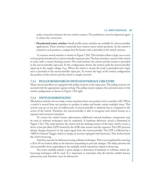
A common switch interface is shown in Figure 7.3(b).This interface allows a logic one or zero<br />
to be properly introduced to a microcontroller input port pin.The basic interface consists of <strong>the</strong> switch<br />
in series <strong>with</strong> a current limiting resistor. The node between <strong>the</strong> switch and <strong>the</strong> resistor is provided<br />
to <strong>the</strong> microcontroller input pin. In <strong>the</strong> configuration shown, <strong>the</strong> resistor pulls <strong>the</strong> microcontroller<br />
input up to <strong>the</strong> supply voltage VDD. When <strong>the</strong> switch is closed, <strong>the</strong> node is grounded and a logic<br />
zero is provided to <strong>the</strong> microcontroller input pin. To reverse <strong>the</strong> logic of <strong>the</strong> switch configuration<br />
<strong>the</strong> position of <strong>the</strong> resistor and <strong>the</strong> switch is simply reversed.<br />
7.3.2 PULLUP RESISTORS IN SWITCH INTERFACE CIRCUITRY<br />
Many microcontrollers are equipped <strong>with</strong> pullup resistors at <strong>the</strong> input pins. The pullup resistors are<br />
asserted <strong>with</strong> <strong>the</strong> appropriate register setting. The pullup resistor replaces <strong>the</strong> external resistor in <strong>the</strong><br />
switch configuration as shown in Figure 7.3b) right.<br />
7.3.3 SWITCH DEBOUNCING<br />
Mechanical switches do not make a clean transition from one position (on) to ano<strong>the</strong>r (off ). When<br />
a switch is moved from one position to ano<strong>the</strong>r, it makes and breaks contact multiple times. This<br />
activity may go on for tens of milliseconds. A microcontroller is relatively fast as compared to <strong>the</strong><br />
action of <strong>the</strong> switch. Therefore, <strong>the</strong> microcontroller is able to recognize each switch bounce as a<br />
separate and erroneous transition.<br />
To correct <strong>the</strong> switch bounce phenomena, additional external hardware components may<br />
be used or software techniques may be employed. A hardware debounce circuit is illustrated in<br />
Figure 7.3(c). The node between <strong>the</strong> switch and <strong>the</strong> limiting resistor of <strong>the</strong> basic switch circuit is<br />
fed to a low pass filter (LPF) formed by <strong>the</strong> 470K ohm resistor and <strong>the</strong> capacitor. The LPF prevents<br />
abrupt changes (bounces) in <strong>the</strong> input signal from <strong>the</strong> microcontroller. The LPF is followed by a<br />
74HC14 Schmitt Trigger, which is simply an inverter equipped <strong>with</strong> hysteresis. This fur<strong>the</strong>r limits<br />
<strong>the</strong> switch bouncing.<br />
Switches may also be debounced using software techniques.This is accomplished by inserting<br />
a 30 to 50 ms lockout delay in <strong>the</strong> function responding to port pin changes. The delay prevents <strong>the</strong><br />
microcontroller from responding to <strong>the</strong> multiple switch transitions related to bouncing.<br />
You must carefully analyze a given design to determine if hardware or software switch debouncing<br />
techniques will be used. It is important to remember that all switches exhibit bounce<br />
phenomena and, <strong>the</strong>refore, must be debounced.