Embedded Systems Design with the Atmel AVR Microcontroller Part II
Embedded Systems Design with the Atmel AVR Microcontroller Part II
Embedded Systems Design with the Atmel AVR Microcontroller Part II

You also want an ePaper? Increase the reach of your titles
YUMPU automatically turns print PDFs into web optimized ePapers that Google loves.
}<br />
7.4. OUTPUT DEVICES 207<br />
//*************************************************************************<br />
//performs specified LCD related command<br />
//*************************************************************************<br />
void putcommand(unsigned char˜(d)<br />
{<br />
DDRC = 0xff; //set PORTC as output<br />
DDRD = DDRD|0xC0; //make PORTD[7:6] output<br />
PORTD = PORTD&0x7f; //RS=0<br />
PORTC = d;<br />
PORTD = PORTD|0x40; //E=1<br />
PORTD = PORTD&0xbf; //E=0<br />
delay_5ms();<br />
}<br />
//*************************************************************************<br />
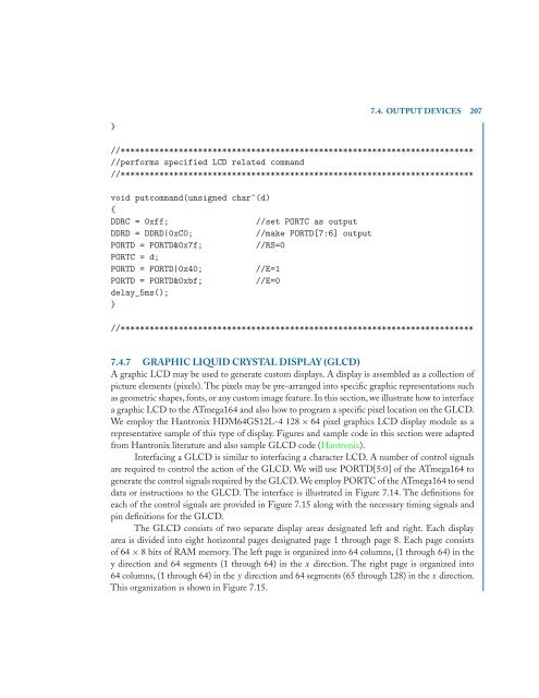
7.4.7 GRAPHIC LIQUID CRYSTAL DISPLAY (GLCD)<br />
A graphic LCD may be used to generate custom displays. A display is assembled as a collection of<br />
picture elements (pixels). The pixels may be pre-arranged into specific graphic representations such<br />
as geometric shapes, fonts, or any custom image feature. In this section, we illustrate how to interface<br />
a graphic LCD to <strong>the</strong> ATmega164 and also how to program a specific pixel location on <strong>the</strong> GLCD.<br />
We employ <strong>the</strong> Hantronix HDM64GS12L-4 128 × 64 pixel graphics LCD display module as a<br />
representative sample of this type of display. Figures and sample code in this section were adapted<br />
from Hantronix literature and also sample GLCD code (Hantronix).<br />
Interfacing a GLCD is similar to interfacing a character LCD. A number of control signals<br />
are required to control <strong>the</strong> action of <strong>the</strong> GLCD. We will use PORTD[5:0] of <strong>the</strong> ATmega164 to<br />
generate <strong>the</strong> control signals required by <strong>the</strong> GLCD. We employ PORTC of <strong>the</strong> ATmega164 to send<br />
data or instructions to <strong>the</strong> GLCD. The interface is illustrated in Figure 7.14. The definitions for<br />
each of <strong>the</strong> control signals are provided in Figure 7.15 along <strong>with</strong> <strong>the</strong> necessary timing signals and<br />
pin definitions for <strong>the</strong> GLCD.<br />
The GLCD consists of two separate display areas designated left and right. Each display<br />
area is divided into eight horizontal pages designated page 1 through page 8. Each page consists<br />
of 64 × 8 bits of RAM memory. The left page is organized into 64 columns, (1 through 64) in <strong>the</strong><br />
y direction and 64 segments (1 through 64) in <strong>the</strong> x direction. The right page is organized into<br />
64 columns, (1 through 64) in <strong>the</strong> y direction and 64 segments (65 through 128) in <strong>the</strong> x direction.<br />
This organization is shown in Figure 7.15.