

Generation C / Génération C - ASCO Numatics
Generation C / Génération C - ASCO Numatics
Generation C / Génération C - ASCO Numatics

Create successful ePaper yourself
Turn your PDF publications into a flip-book with our unique Google optimized e-Paper software.
00455GB-2007/R01<br />
Availability, design and specifi cations are subject to change without notice. All rights reserved.<br />
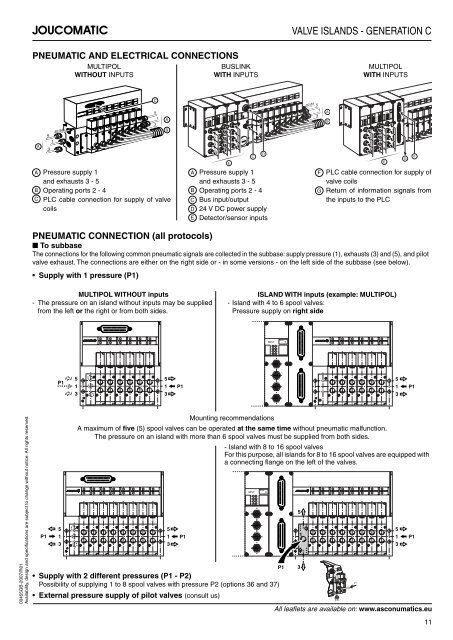
PNEUMATIC AND ELECTRICAL CONNECTIONS<br />
A<br />
5<br />
1<br />
3<br />
82-84<br />
MULTIPOL<br />
WITHOUT INPUTS<br />
A Pressure supply 1<br />
and exhausts 3 - 5<br />
B Operating ports 2 - 4<br />
C PLC cable connection for supply of valve<br />
coils<br />
MULTIPOL WITHOUT inputs<br />
- The pressure on an island without inputs may be supplied<br />
from the left or the right or from both sides.<br />
P1<br />
5<br />
1<br />
3<br />
C<br />
5<br />
3<br />
1<br />
A<br />
B<br />
BUSLINK<br />
WITH INPUTS<br />
VALVE ISLANDS - GENERATION C<br />
ISLAND WITH inputs (example: MULTIPOL)<br />
- Island with 4 to 6 spool valves:<br />
Pressure supply on right side<br />
Mounting recommendations<br />
A maximum of fi ve (5) spool valves can be operated at the same time without pneumatic malfunction.<br />
The pressure on an island with more than 6 spool valves must be supplied from both sides.<br />
Supply with 2 different pressures (P1 - P2)<br />
Possibility of supplying 1 to 8 spool valves with pressure P2 (options 36 and 37)<br />
External pressure supply of pilot valves (consult us)<br />
5<br />
1<br />
3<br />
5<br />
5<br />
P1 1<br />
1 P1<br />
3<br />
3<br />
P1<br />
INPUT<br />
0<br />
2<br />
4<br />
6<br />
BYTE<br />
1<br />
3<br />
5<br />
7<br />
BYTE<br />
BYTE<br />
I<br />
N<br />
P<br />
U<br />
T<br />
E<br />
+ 5V<br />
+ 24V<br />
RUN I/O<br />
COM ERR<br />
A Pressure supply 1<br />
and exhausts 3 - 5<br />
B Operating ports 2 - 4<br />
C Bus input/output<br />
D 24 V DC power supply<br />
E Detector/sensor inputs<br />
INPUT<br />
PNEUMATIC CONNECTION (all protocols)<br />
■ To subbase<br />
The connections for the following common pneumatic signals are collected in the subbase: supply pressure (1), exhausts (3) and (5), and pilot<br />
valve exhaust. The connections are either on the right side or - in some versions - on the left side of the subbase (see below).<br />
Supply with 1 pressure (P1)<br />
BYTE<br />
Pg21<br />
C<br />
INPUT 0<br />
0<br />
2<br />
4<br />
6<br />
1<br />
3<br />
5<br />
7<br />
5<br />
1 P1<br />
3<br />
- Island with 8 to 16 spool valves<br />
For this purpose, all islands for 8 to 16 spool valves are equipped with<br />
a connecting fl ange on the left of the valves.<br />
INPUT 0<br />
0<br />
2<br />
4<br />
6<br />
1<br />
3<br />
5<br />
7<br />
D<br />
P1<br />
5<br />
3<br />
1<br />
82-84<br />
5<br />
1<br />
3<br />
A<br />
B<br />
MULTIPOL<br />
WITH INPUTS<br />
INPUT<br />
0<br />
2<br />
4<br />
6<br />
BYTE<br />
1<br />
3<br />
5<br />
7<br />
BYTE<br />
F PLC cable connection for supply of<br />
valve coils<br />
G Return of information signals from<br />
the inputs to the PLC<br />
+ 5V<br />
+ 24V<br />
RUN/MOD<br />
ERR/NET<br />
Pg21<br />
5<br />
1<br />
3<br />
P1<br />
BYTE<br />
I<br />
N<br />
P<br />
U<br />
T<br />
E<br />
INPUT<br />
BYTE<br />
5<br />
1<br />
3<br />
5<br />
1<br />
3<br />
All leafl ets are available on: www.asconumatics.eu<br />
G<br />
F<br />
P1<br />
11


