

Generation C / Génération C - ASCO Numatics
Generation C / Génération C - ASCO Numatics
Generation C / Génération C - ASCO Numatics

Create successful ePaper yourself
Turn your PDF publications into a flip-book with our unique Google optimized e-Paper software.
00455GB-2007/R01<br />
Availability, design and specifi cations are subject to change without notice. All rights reserved.<br />
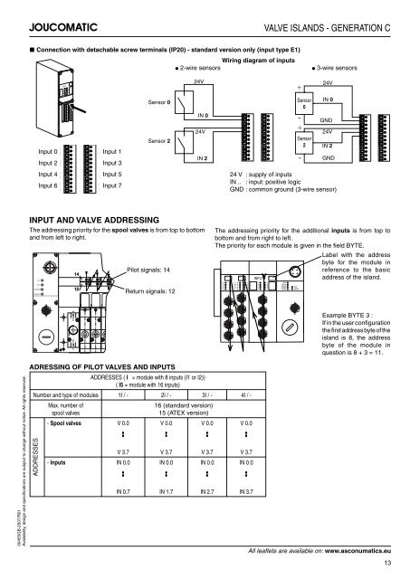
■ Connection with detachable screw terminals (IP20) - standard version only (input type E1)<br />
Input 0<br />
Input 2<br />
Input 4<br />
Input 6<br />
INPUT<br />
0<br />
2<br />
4<br />
6<br />
1<br />
3<br />
5<br />
7<br />
Input 1<br />
Input 3<br />
Input 5<br />
Input 7<br />
Sensor 0<br />
Sensor 2<br />
INPUT AND VALVE ADDRESSING<br />
The addressing priority for the spool valves is from top to bottom<br />
and from left to right.<br />
+ 5V<br />
+ 24V<br />
RUN/MOD<br />
ERR/NET<br />
1<br />
5<br />
3<br />
14<br />
12<br />
Pilot signals: 14<br />
Return signals: 12<br />
ADRESSING OF PILOT VALVES AND INPUTS<br />
VALVE ISLANDS - GENERATION C<br />
Wiring diagram of inputs<br />
● 2-wire sensors ● 3-wire sensors<br />
24V 24V<br />
IN 0<br />
IN 2<br />
+<br />
Sensor<br />
0<br />
-<br />
+<br />
-<br />
IN 0<br />
GND<br />
24V 24V<br />
Sensor<br />
2 IN 2<br />
BYTE BYTE<br />
0 1 I 0 1<br />
2 3 N 2 3<br />
P<br />
4 5 U 4 5<br />
6 7 T 6 7<br />
ADDRESSES ( I = module with 8 inputs (I1 or I2))<br />
( I5 = module with 16 inputs)<br />
Number and type of modules 1I / - 2I / - 3I / - 4I / -<br />
ADDRESSES<br />
Max. number of<br />
spool valves<br />
16 (standard version)<br />
15 (ATEX version)<br />
- Spool valves V 0.0 V 0.0 V 0.0 V 0.0<br />
V 3.7 V 3.7 V 3.7 V 3.7<br />
- Inputs IN 0.0 IN 0.0 IN 0.0 IN 0.0<br />
IN 0.7 IN 1.7 IN 2.7 IN 3.7<br />
INPUT<br />
0 1<br />
2 3<br />
4 5<br />
6 7<br />
BYTE<br />
+5V<br />
+24V<br />
RUN I/O<br />
COM ERR<br />
GND<br />
24 V : supply of inputs<br />
IN .. : input: positive logic<br />
GND : common ground (3-wire sensor)<br />
The addressing priority for the additional inputs is from top to<br />
bottom and from right to left.<br />
The priority for each module is given in the fi eld BYTE.<br />
Label with the address<br />
byte for the module in<br />
reference to the basic<br />
address of the island.<br />
Example BYTE 3 :<br />
If in the user confi guration<br />
the fi rst address byte of the<br />
island is 8, the address<br />
byte of the module in<br />
question is 8 + 3 = 11.<br />
All leafl ets are available on: www.asconumatics.eu<br />
13


