

Generation C / Génération C - ASCO Numatics
Generation C / Génération C - ASCO Numatics
Generation C / Génération C - ASCO Numatics

Create successful ePaper yourself
Turn your PDF publications into a flip-book with our unique Google optimized e-Paper software.
■ Setting of the transmission speed<br />
The transmission speed does not need to be adjusted, it is fi xed at 1 MBaud.<br />
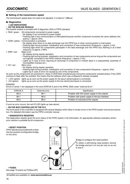
RESET POSITION<br />
FIPIO islands are provided with a reset<br />
into zero position (confi guration bridge<br />
on two pins)<br />
FUSES<br />
See page 19 (same as Profi bus-DP)<br />
+ 5 V<br />
+ 24 V<br />
RUN I/O<br />
COM ERR<br />
VALVE ISLANDS - GENERATION C<br />
■ Diagnostics<br />
LED INDICATIONS<br />
- ON THE BUSLINK MODULE<br />
The buslink module is provided with 6 diagnostic LEDs to FIPIO standard.<br />
RUN / green: All components connected to power supply<br />
- No display if not connected to power supply<br />
- Flashing light if bus communication is interrupted because another component accesses the same address (frequency<br />
= approx. 2Hz).<br />
COM / yellow : Communication is activated.<br />
- No display when there is no data exchange over the FIPIO bus or when communication is interrupted.<br />
- Flashing light during autotest, initialisation and connection of new components (Frequency = approx. 2 Hz).<br />
- Flashing light when the components participate in the data exchange over the FIPIO bus; fl ashing is at a fi xed<br />
frequency of approx. 2 MHz.<br />
ERR / red: Major error<br />
- No display during regular operation.<br />
- Flashing light during autotest, initialisation and connection of new components and as long as the components are<br />
not logically connected to the FIPIO network (frequency = approx. 2 Hz).<br />
- Lights up in case of error requiring an exchange of component or module (fault in a subassembly, assembly of<br />
incompatible modules etc.)<br />
I/O / red : Minor error<br />
- No display during regular operation.<br />
- Flashing light during autotest, initialisation and connection of new components (frequency = approx. 2Hz).<br />
- Lights fup in case of error not caused by one of the components.<br />
As soon as the components are powered-on, these 4 LEDS fl ash simultaneously during the components' autotest phase. If the LEDS<br />
continue to fl ash after the autotest, this means that the address which was confi gured is already occupied.<br />
+ 24V (green) lights up as soon as the power supply for the spool valves/outputs is connected.<br />
+5V (green) lights up as soon as the power supply to the bus electronics/inputs is connected.<br />
ERRORS<br />
Errors in series 7 are displayed in the word STATUS A and in the APRIL 5000 under "external Error".<br />
STATUS A External error Signifi cation<br />
Bit 3 Bit 1 Problem with 24V power supply to the outputs<br />
Bit 1 Bit 3 Problem with power supply to the bus interface<br />
Bit 0 Bit 4 Problem of overload at the outputs<br />
If such an error occurs, the red I/O LED lights up (see above)<br />
- ON THE BUS CONTROLLER OF THE PLC<br />
The front panel of the controller is equipped with several displays which allow to locate errors in the FIPIO system and sensors/actuators.<br />
For detailed information see the FIPIO controller manual.<br />
DIAGNOSTICS REGISTER<br />
The diagnostics register gives the error status of the FIPIO system in bit information. An appropriate software evaluation and/or<br />
error reaction is possible by bit comparison.<br />
All leafl ets are available on: www.asconumatics.eu<br />
26<br />
Bridge to confi gure the reset position<br />
To obtain a self-locking reset position remove<br />
the bridge and put it on one pin only so as not<br />
to lose it.<br />
00236GB-2005/R01<br />
Availability, design and specifi cations are subject to change without notice. All rights reserved.


