

Generation C / Génération C - ASCO Numatics
Generation C / Génération C - ASCO Numatics
Generation C / Génération C - ASCO Numatics

You also want an ePaper? Increase the reach of your titles
YUMPU automatically turns print PDFs into web optimized ePapers that Google loves.
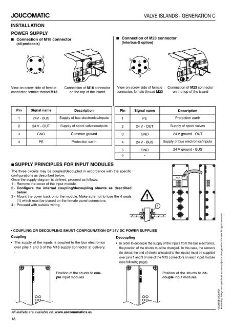
INSTALLATION<br />
POWER SUPPLY<br />
■ Connection of M18 connector<br />
(all protocols)<br />
2<br />
View on screw side of female<br />
connector, female thread M18<br />
Pin Signal name<br />
1 24V - BUS<br />
2 24 V - OUT<br />
3 GND<br />
4 PE<br />
3<br />
1 4<br />
INPUT<br />
0<br />
2<br />
4<br />
6<br />
BYTE<br />
1<br />
3<br />
5<br />
7<br />
+ 5V<br />
+ 24V<br />
RUN<br />
COM<br />
I/O<br />
ERR<br />
Connection of M18 connector<br />
on the top of the island<br />
Supply of bus electronics/inputs<br />
Supply of spool valves/outputs<br />
Common ground<br />
Protection earth<br />
■ SUPPLY PRINCIPLES FOR INPUT MODULES<br />
VALVE ISLANDS - GENERATION C<br />
■ Connection of M23 connector<br />
(Interbus-S option)<br />
Description Pin Signal name<br />
The three circuits may be coupled/decoupled in accordance with the specifi c<br />
confi gurations as described below.<br />
Once the supply diagram is defi ned, proceed as follows:<br />
1 - Remove the cover of the input module.<br />
2 - Confi gure the internal coupling/decoupling shunts as described<br />
below.<br />
3 - Mount the cover back onto the module. Make sure not to lose the 4 seals<br />
(1) which must be placed on the female panel connectors.<br />
4 - Proceed with outside wiring.<br />
5<br />
4<br />
6<br />
3<br />
View on screw side of female<br />
connector, female thread M23<br />
1 PE<br />
2 24 V - OUT<br />
3 GND<br />
4 24 V - BUS<br />
5 GND<br />
6 -<br />
COUPLING OR DECOUPLING SHUNT CONFIGURATION OF 24V DC POWER SUPPLIES<br />
Coupling<br />
The supply of the inputs is coupled to the bus electronics<br />
over pins 1 and 3 of the M18 supply connector at delivery.<br />
.<br />
Position of the shunts to couple<br />
input modules<br />
All leafl ets are available on: www.asconumatics.eu<br />
18<br />
Decoupling<br />
1<br />
!<br />
2<br />
1<br />
INPUT<br />
0<br />
2<br />
4<br />
6<br />
BYTE<br />
1<br />
3<br />
5<br />
7<br />
+ 5V<br />
+ 24V<br />
RUN<br />
COM<br />
Connection of M23 connector<br />
on the top of the island<br />
Description<br />
Protection earth<br />
Supply of spool valves<br />
24 V ground - OUT<br />
Supply of bus electronics/inputs<br />
24 V ground - BUS<br />
In order to decouple the supply of the inputs from the bus electronics,<br />
the position of the shunts must be changed. In this case, the sensors<br />
(to detect the end of stroke allocated to the inputs) must be supplied<br />
over pins 1 and 3 of one of the M12 connectors on each input module<br />
(see following page).<br />
INPUT<br />
0<br />
2<br />
4<br />
6<br />
1<br />
3<br />
5<br />
7<br />
0<br />
-<br />
I/O<br />
ERR<br />
Position of the shunts to decouple<br />
input modules<br />
00236GB-2005/R01<br />
Availability, design and specifi cations are subject to change without notice. All rights reserved.


