

Generation C / Génération C - ASCO Numatics
Generation C / Génération C - ASCO Numatics
Generation C / Génération C - ASCO Numatics

You also want an ePaper? Increase the reach of your titles
YUMPU automatically turns print PDFs into web optimized ePapers that Google loves.
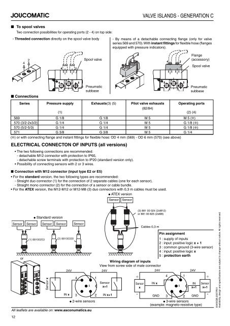
■ To spool valves<br />
Two connection possibilities for operating ports (2 - 4) on top side:<br />
4 2<br />
■ Connections<br />
Series<br />
Pressure supply<br />
(1)<br />
4<br />
Exhausts(3) (5) Pilot valve exhausts<br />
(82/84)<br />
2<br />
VALVE ISLANDS - GENERATION C<br />
- Threaded connection directly on the spool valve body - By means of a detachable connecting fl ange (only for valve<br />
series 569 and 570). With instant fi ttings for fl exible hose (fl anges<br />
equipped with pressure indicators).<br />
Operating ports<br />
(2) (4)<br />
569 G 1/8 G 1/8 M 5 M 5 (❇)<br />
570 (3/2-2x3/2)<br />
570 (5/2-5/3)<br />
G 1/4<br />
G 1/4<br />
G 1/4<br />
G 1/4<br />
M 5<br />
M 5<br />
G 1/8 (❇)<br />
G 1/8 (❇)<br />
571 G 3/8 G 3/8 M 5 G 1/4<br />
(❇) or with connecting fl ange and instant fi ttings for fl exible hose: OD 4 mm (569) - OD 6 mm (570) (see above)<br />
ELECTRICAL CONNECTON OF INPUTS (all versions)<br />
The two following connections are recommended:<br />
- detachable M12 connector with protection to IP65,<br />
- detachable screw terminals with protection to IP20 (standard version only).<br />
Possibility of connecting sensors with 2 or 3 wires.<br />
■ Connection with M12 connector (input type E2 or E5)<br />
For the standard version, the two following types are recommended:<br />
- Straight duo connector (1) for the connection of 2 separate cables (one for each sensor).<br />
- Straight mono connector (2) for the connection of a sensor or cable bundle.<br />
For the ATEX version, the M12-M12 or M12-M8 (3) duo connectors with 0,3 m cables must be used.<br />
● ATEX version<br />
Sensor<br />
or<br />
BYTE<br />
BYTE<br />
I<br />
N<br />
P<br />
U<br />
T<br />
● Standard version<br />
Sensor Sensor Sensor Sensor<br />
(1) 88100253<br />
INPUT<br />
0<br />
2<br />
4<br />
6<br />
1<br />
3<br />
5<br />
7<br />
Sensor x<br />
(2) 88100330<br />
IN x 3<br />
2 IN x+1<br />
All leafl ets are available on: www.asconumatics.eu<br />
12<br />
Spool valve<br />
Pneumatic<br />
subbase<br />
5<br />
Sensor<br />
x+1<br />
Sensor Sensor<br />
(3) 881 00 024 (2xM12)<br />
(3) 88100824 (2xM12)<br />
or 881 00 825 (2xM8)<br />
ou 88100825 (2xM8)<br />
Sensor<br />
x<br />
-<br />
Cables 0,3 m<br />
IN x<br />
Pin assignment<br />
1 : supply of inputs<br />
2 : input: positive logic x + 1<br />
3 : common ground (3-wire sensor)<br />
4 : input: positive logic x<br />
5 : protection earth<br />
Wiring diagram of inputs<br />
View from screw side of male connector<br />
24V 24V 24V 24V<br />
+<br />
4 1<br />
4<br />
1<br />
+<br />
GND 3 2 GND<br />
5<br />
Flange<br />
(accessory)<br />
Spool valve<br />
Pneumatic<br />
subbase<br />
IN<br />
x+1<br />
● 2-wire sensors ● 3-wire sensors<br />
(example: magneto-resistive type)<br />
Sensor<br />
x+1<br />
-<br />
00455GB-2007/R01<br />
Availability, design and specifi cations are subject to change without notice. All rights reserved.


