

Generation C / Génération C - ASCO Numatics
Generation C / Génération C - ASCO Numatics
Generation C / Génération C - ASCO Numatics

You also want an ePaper? Increase the reach of your titles
YUMPU automatically turns print PDFs into web optimized ePapers that Google loves.
■ Programming instructions<br />
9<br />
24V =<br />
VALVE ISLANDS - GENERATION C<br />
For detailed programming instructions see the PLC and Interbus-S controller manuals.<br />
The addresses for the Buslink module are confi gured on the Interbus-S controller. Set the basic address (BA) and the window size<br />
with the dip switches. The addresses are not set on the spool valve island.<br />
Automatic addressing: The address assignment is exclusively linked to the spool valve island's position in the bus system.<br />
Standard software is available and provided with the Phoenix Contact controller module.<br />
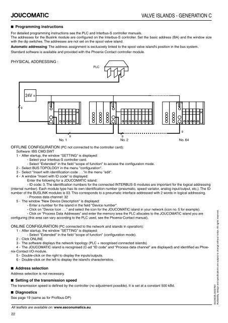
PHYSICAL ADDRESSING :<br />
PLC<br />
9 9<br />
No. 1 No. 2 No. 64<br />
OFFLINE CONFIGURATION (PC not connected to the controller card):<br />
Software: IBS CMD.SWT<br />
1 - After startup, the window "SETTING" is displayed:<br />
- Select your Interbus-S controller card.<br />
- Select "Extended" in the fi eld "scope of function" to access the confi guraton mode.<br />
2 - Select BUS TOPOLOGY in the menu "confi guration".<br />
3 - Select "Insert with identifi cation code . . ."in the menu "edit".<br />
4 - A window "Insert with ID code" is displayed:<br />
Enter the following for a JOUCOMATIC island:<br />
- ID code: 3. The identifi cation numbers for the connected INTERBUS-S modules are important for the logical addressing<br />
(internal number). Each module type has its own identifi cation number (pneumatic, speed variator, analog input/output, etc,). The ID<br />
number of the BUSLINK modules is 03. This corresponds to a pneumatic interface addressed with 2 words in logical addressing.<br />
- Process data channel: 32<br />
5 - The window "New Device Description" is displayed:<br />
- Enter a number for the island in the fi eld "Device number".<br />
- Click on "Device Icon . . ." and select the icon for the JOUCOMATIC island in your network (icon no. 5 for example).<br />
- Click on "Process Data Addresses" and enter the memory area the PLC allocates to the JOUCOMATIC island you are<br />
confi guring (this area can vary according to the PLC used, see the Phoenix-Contact manual).<br />
ONLINE CONFIGURATION (PC connected to the network and islands in operation):<br />
1 - After startup, the window "SETTING" is displayed:<br />
- Select "Extended" in the fi eld "scope of function" (confi guration mode).<br />
2 - Click ONLINE<br />
3 - The software displays the network topology (PLC + recognised connected islands)<br />
4 - The JOUCOMATIC island is recognised (C-ad "ID code" and "Process data channel" are displayed) and identifi ed as Phoenix-Contact<br />
I/O module.<br />
5 - Double-click on the right to display the inputs/outputs.<br />
6 - Double-click on the left to display the island's characteristics.<br />
■ Address selection<br />
Address selection is not necessary.<br />
■ Setting of the transmission speed<br />
The transmission speed is defi ned by the controller (no adjustment possible). It is set at a constant 500 kBd.<br />
■ Diagnostics<br />
See page 19 (same as for Profi bus-DP)<br />
All leafl ets are available on: www.asconumatics.eu<br />
22<br />
9<br />
00236GB-2005/R01<br />
Availability, design and specifi cations are subject to change without notice. All rights reserved.


