

Generation C / Génération C - ASCO Numatics
Generation C / Génération C - ASCO Numatics
Generation C / Génération C - ASCO Numatics

You also want an ePaper? Increase the reach of your titles
YUMPU automatically turns print PDFs into web optimized ePapers that Google loves.
00236GB-2005/R01<br />
Availability, design and specifi cations are subject to change without notice. All rights reserved.<br />
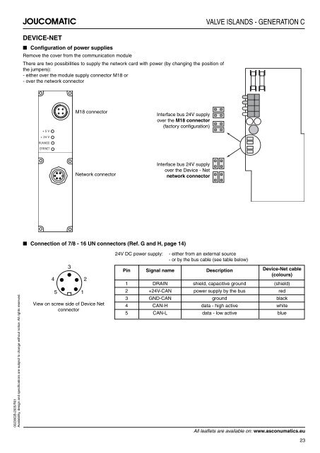
DEVICE-NET<br />
■ Confi guration of power supplies<br />
Remove the cover from the communication module<br />
There are two possibilities to supply the network card with power (by changing the position of<br />
the jumpers):<br />
- either over the module supply connector M18 or<br />
- over the network connector<br />
+ 5 V<br />
+ 24 V<br />
RUN/MOD<br />
ERR/NET<br />
■ Connection of 7/8 - 16 UN connectors (Ref. G and H, page 14)<br />
4<br />
3<br />
5 1<br />
M18 connector<br />
Network connector<br />
View on screw side of Device Net<br />
connector<br />
2<br />
Interface bus 24V supply<br />
over the M18 connector<br />
(factory confi guration)<br />
Interface bus 24V supply<br />
over the Device - Net<br />
network connector<br />
24V DC power supply: - either from an external source<br />
- or by the bus cable (see table below)<br />
VALVE ISLANDS - GENERATION C<br />
Pin Signal name Description Device-Net cable<br />
(colours)<br />
1 DRAIN shield, capacitive ground (shield)<br />
2 +24V-CAN power supply by the bus red<br />
3 GND-CAN ground black<br />
4 CAN-H data - high active white<br />
5 CAN-L data - low active blue<br />
All leafl ets are available on: www.asconumatics.eu<br />
23


