Report - Oregon State Library: State Employee Information Center ...
Report - Oregon State Library: State Employee Information Center ...
Report - Oregon State Library: State Employee Information Center ...

You also want an ePaper? Increase the reach of your titles
YUMPU automatically turns print PDFs into web optimized ePapers that Google loves.
6.2 PORE PRESSURE GENERATION<br />
The pore pressure generation scheme is based on empirical procedures developed by Seed and<br />
others over the last 25 years (Martin et al. 1975; Seed et al. 1976, 1979). The pore pressure<br />
model was initially developed by Roth and his co-workers for use in a variety of earthquake<br />
engineering applications (Roth et al. 1986, 1991, 1992, 1994; Roth and Inel 1993; Inel et al.<br />
1993). During each time-step of the dynamic analysis, the effective stresses decrease and pore<br />
pressures gradually increase in liquefiable soils, until a state of full liquefaction is reached.<br />
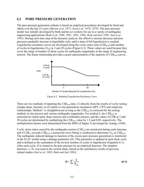
Liquefaction resistance curves are developed using the cyclic stress ratio (CSR field ) and number<br />
of cycles to liquefaction (N liq ) at 3 and 30 cycles (Figure 6.2). These values are used because they<br />
cover the range of number of shear cycles for earthquake magnitudes in the range of engineering<br />
interest. The linear relationship provides a good representation of the majority of CSR field curves.<br />
CSR<br />
CSR @<br />
3 cycles<br />
CSR @<br />
30 cycles<br />
3 30<br />
Number of Cycles Required for Liquefaction (N liz)<br />
Figure 6.2: Modeled Liquefaction Resistance Curve<br />
There are two methods of inputting the CSR field data: (1) directly from the results of cyclic testing<br />
(simple shear, triaxial), or (2) utilize in situ penetration resistances (SPT, CPT) and empirical<br />
relationships. Method 1 is straightforward as long as the CSR field is corrected for the testing<br />
method, in situ stresses and various earthquake magnitudes. For method 2, the CSR field is<br />
corrected for initial static shear stresses and overburden stresses, and the values of CSR at 3 and<br />
30 cycles are determined by multiplying the CSR field value by 1.5 and 0.89, respectively. The<br />
multiplication factors were determined from the MSFs (Chapter 3) developed by Arango (1996).<br />
Cyclic stress ratios caused by the earthquake motion (CSR eq ) are monitored during each timestep,<br />
and if CSR eq exceeds CSR field , a numerical curve fitting is conducted to determine N liq at CSR field .<br />
The earthquake-induced damage (a function of the excess pore pressure generation) is monitored<br />
in the FLAC model using a damage parameter (D). This parameter is updated at each shear cycle<br />
and is defined as the summation of the inverse number of cycles to liquefaction (Equation 6-1).<br />
After each cycle, D is related to the pore pressure by an empirical function. The simplest<br />
function, r u =D, was used in the current study, based on the satisfactory results of previous<br />
related studies (Inel et al. 1993; Roth and Inel 1993).<br />
D <br />
1<br />
N liq<br />
(6-1)<br />
111