Report - Oregon State Library: State Employee Information Center ...
Report - Oregon State Library: State Employee Information Center ...
Report - Oregon State Library: State Employee Information Center ...

You also want an ePaper? Increase the reach of your titles
YUMPU automatically turns print PDFs into web optimized ePapers that Google loves.
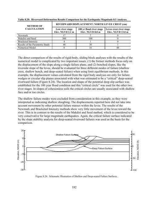
Table 8.20: Riverward Deformation Results Comparison for the Earthquake Magnitude 8.5 Analyses.<br />
METHOD OF<br />
CALCULATION<br />
RIVERWARD DISPLACEMENT: NORTH LEVEE CREST (cm)<br />
Low river stage<br />
Elev. NGVD 2.1 m<br />
100 yr flood river stage<br />
Elev. NGVD 8.8 m<br />
Newmark 17 7 0<br />
Makdisi and Seed 300 100 0<br />
Bracketed Intensity 4 1 0<br />
Results of the Parametric Study 40 30 1<br />
Numerical Model 0 16 48<br />
Levee crest river stage<br />
Elev. NGVD 13.0 m<br />
The direct comparison of the results of rigid-body, sliding block analyses with the results of the<br />
numerical model is complicated by two important issues; (1) the former methods focus only on<br />
the displacement of the slope along a single failure plane, and (2) benched slopes, like the<br />
riverside slope of the levee, should be evaluated for three different modes of failure (shallow<br />
crest, shallow bench, and deep-seated failure) when using limit equilibrium methods. In this<br />
example, the displacement values calculated from the rigid body analyses are only for failure<br />
wedges or circular slip planes associated with what was estimated to be a “critical” deep-seated<br />
riverward failure (Figure 8.24). The location and shape of the potential deep slip surface was<br />
established for the 100 year flood condition and this “critical circle” was used for the other two<br />
river stages. In slopes of cohesionless soils the critical circles are usually associated with shallow<br />
face and/or toe circles.<br />
The shallow failure modes were excluded from consideration in this example, as they were<br />
interpreted as indicating shallow sloughing. The displacements reported here did not take into<br />
account movement by other potential failure masses within the levee. The results of the<br />
Newmark and Bracketed Intensity methods show very little movement of the levee toward the<br />
river. This is in contrast to the results of the Makdisi and Seed method, which is considered to be<br />
very conservative for large magnitude earthquakes. Again, the critical failure surface indicated<br />
by the slope stability analysis for deep-seated riverward failures was used as the basis for the<br />
comparison.<br />
20<br />
Shallow Failure Surface<br />
50<br />
10<br />
Elevation, NGVD (m)<br />
0<br />
-10<br />
Deep Failure Surface<br />
0<br />
-50<br />
Elevation, NGVD (ft)<br />
-20<br />
-30<br />
-100<br />
Figure 8.24: Schematic Illustration of Shallow and Deep-seated Failure Surfaces.<br />
182