- Page 1:
Charge Transfer Dynamics in Quantum
- Page 7:
DECLARATION I, hereby declare that
- Page 11:
ACKNOWLEDGEMENTS It is my privilege
- Page 14 and 15:
1.3.5. Defect Mediated Relaxation 2
- Page 16 and 17:
2. 8. 4. White Light Generation- 45
- Page 18 and 19:
6.2. Experimental 6.2.1.Synthesis o
- Page 20 and 21:
devices based on QDs it has been sh
- Page 22 and 23:
Furthermore generation of pump (~40
- Page 24 and 25:
shell). This clearly indicated that
- Page 26 and 27:
12. V. I. Klimov, J. Phys. Chem. B,
- Page 28 and 29:
1.13 Reactant and Product Potential
- Page 30 and 31:
light. Inset: Kinetic traces monito
- Page 32 and 33:
6.5 Transient decay kinetics of gra
- Page 34 and 35:
at 670 nm after exciting at 400 nm
- Page 37 and 38:
ABBREVIATIONS BET BQ CB CCD CdS CdT
- Page 39:
1 Chapter 1
- Page 42 and 43:
3 size dependent optical properties
- Page 44 and 45:
5 1.2. Physics of Semiconductors 1.
- Page 46 and 47:
7 As seen from the schematic, poten
- Page 48 and 49:
9 Substituting this in Schrödinger
- Page 50 and 51:
11 ( r, r ) ( r ) ( r ) (1.13) e
- Page 52 and 53:
13 E E E 2 2 2 EX ne, le nh,
- Page 54 and 55:
15 spherical symmetry of field. The
- Page 56 and 57:
17 gE ( ) 2Em 2 3 3 (1.25) For a
- Page 58 and 59:
19 1.3.2. Electron-Hole energy tran
- Page 60 and 61:
21 Impact Ionization Figure 1.7. Sc
- Page 62 and 63:
23 understanding on mechanistic asp
- Page 64 and 65:
25 carriers are unable to sample th
- Page 66 and 67:
27 CB VB QD Metal Figure. 1. 10. Sc
- Page 68 and 69:
29 energy barrier. Therefore it is
- Page 70 and 71:
31 1 f q 2 A qB (1.30) 2 In equa
- Page 72 and 73:
33 Vibrational contribution can be
- Page 74 and 75:
35 1. 7. 1. Electron Injection ET i
- Page 76 and 77:
37 Under assumption of invariance o
- Page 78 and 79:
39 distribution. To achieve good si
- Page 80 and 81:
41 initially achieved monodispersit
- Page 82 and 83:
43 and rate of charge transfer acro
- Page 84 and 85:
45 1.32 P. V. Kamat, J. Phys. Chem.
- Page 87:
47 Chapter 2
- Page 90 and 91:
49 chemical species. Since a partic
- Page 92 and 93:
51 fluorescence forms an important
- Page 94 and 95:
53 eliminated by use of standard wh
- Page 96 and 97:
55 sample. Raman spectroscopy is ba
- Page 98 and 99:
57 will appear bright and region wi
- Page 100 and 101:
59 volatile solvent is drop casted
- Page 102 and 103:
61 spots arise from diffraction fro
- Page 104 and 105:
63 The electrical signal is then ch
- Page 106 and 107:
65 delayed and inverted. The two si
- Page 108 and 109:
67 Pump-probe technique is one of t
- Page 110 and 111:
69 Amplifier Jade Stretcher fs Osci
- Page 112 and 113:
71 Figure 2.6. Optical layout of Ti
- Page 114 and 115:
73 Grating Convex Mirror Concave Mi
- Page 116 and 117:
75 changes the polarization from ho
- Page 118 and 119:
77 Grating Output Input Mirror Grat
- Page 120 and 121:
79 μJ has a very high peak power.
- Page 122 and 123:
81 2.6. Dynamical Theory of X-Ray D
- Page 125:
83 Chapter 3
- Page 128 and 129:
85 Therefore the study of interfaci
- Page 130 and 131:
87 3. 2. Experimental Section 3.2.1
- Page 132 and 133:
89 and intensity show absence of ot
- Page 134 and 135: 91 which is also neutral; therefore
- Page 136 and 137: 93 electron transfer times. This re
- Page 138 and 139: 95 r B a * 0 3.1 me / me Now the
- Page 140 and 141: 97 nonadiabatic case the electron t
- Page 142 and 143: 99 drastically reduced leading to a
- Page 144 and 145: 101 While the study of injection dy
- Page 146 and 147: 103 study. Based on the injection d
- Page 148 and 149: 105 17. L. E. Brus, J. Phys. Chem.
- Page 151: 107 Chapter 4
- Page 154 and 155: 109 of the QDs. As a result surface
- Page 156 and 157: 111 4.2.2. Synthesis: The CdTe QDs
- Page 158 and 159: 113 lower hole state. In CdSe the l
- Page 160 and 161: 115 4.2 inset. The kinetic traces a
- Page 162 and 163: 117 growth of the bleach kinetics (
- Page 164 and 165: 119 previous section we have discus
- Page 166 and 167: 121 lived charge transfer complex w
- Page 168 and 169: 123 100 times concentration of the
- Page 170 and 171: 125 4.5. References 4.1. Efros, Al.
- Page 173: 127 Chapter 5
- Page 176 and 177: 129 been made in the synthesis of t
- Page 178 and 179: 131 metallic synthesis by arrested
- Page 180 and 181: 133 5.3. Result and discussion: 5.3
- Page 182 and 183: 135 indicating a confinement induce
- Page 186 and 187: 139 1000 c b PL Intensity 100 10 a
- Page 188 and 189: 141 samples due to a very weak exci
- Page 190 and 191: 143 dynamical spectrum is negligibl
- Page 192 and 193: 145 Earlier authors [5.4] reported
- Page 194 and 195: 147 Sample t r(ps) t 1(ps) t 2(ps)
- Page 196 and 197: 149 In addition to the cooling dyna
- Page 198 and 199: 151 pulse-width time scale followed
- Page 200 and 201: 153 5.20. Sreejith Kaniyankandy, Sa
- Page 203 and 204: 155 CHAPTER 6 Charge Separation in
- Page 205 and 206: 157 Studies by Wang et. al. [6.15]
- Page 207 and 208: 159 graphene in a 1M NaOH solution.
- Page 209 and 210: 161 Intensity (a.u.) 5 4 3 2 1 CdTe
- Page 211 and 212: 163 dynamics of graphene oxide and
- Page 213 and 214: 165 GO as shown in the Figure 3 rev
- Page 215 and 216: 167 electron acceptor for Graphene.
- Page 217 and 218: 169 governs the recombination dynam
- Page 219 and 220: 171 Sample τ 1 (ps) τ 2 (ps) τ 3
- Page 221 and 222: 173 A (mO.D) 10.0 0.0 -10.0 -20.0 0
- Page 223 and 224: 175 involved in the relaxation may
- Page 225 and 226: 177 Electron quencher (benzoquinone
- Page 227 and 228: 179 Scheme 6.1. Schematic of Electr
- Page 229 and 230: 181 6.6. Reina, A.; Jia, X.; Ho, J.
- Page 231: 183 6.26. Kaiser, A. B.; Navarro, C
- Page 234 and 235:
185 assigned to injection into diff
- Page 236 and 237:
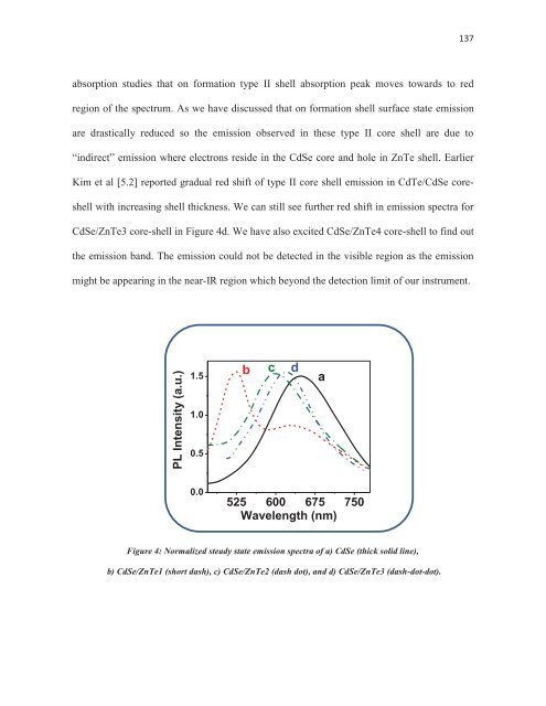
187 transfer from CdSe core to ZnTe
- Page 238 and 239:
189 However the position of bands i