MA-500TR Instruction Manual - ICOM Canada
MA-500TR Instruction Manual - ICOM Canada
MA-500TR Instruction Manual - ICOM Canada

You also want an ePaper? Increase the reach of your titles
YUMPU automatically turns print PDFs into web optimized ePapers that Google loves.
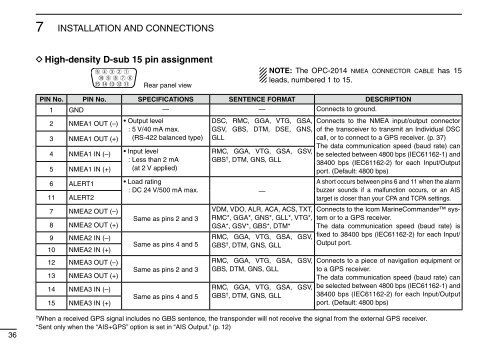
7 INSTALLATION AND CONNECTIONS<br />
D High-density D-sub 15 pin assignment<br />
trewq<br />
!0 oiu y<br />
!5 !4 !3 !2 !1<br />
Rear panel view<br />
NOTE: The OPC-2014 nmea connector cable has 15<br />
leads, numbered 1 to 15.<br />
PIN No. PIN No. SPECIFICATIONS SENTENCE FOR<strong>MA</strong>T DESCRIPTION<br />
1 GND — — Connects to ground.<br />
2 NMEA1 OUT (–)<br />
3 NMEA1 OUT (+)<br />
4 NMEA1 IN (–)<br />
5 NMEA1 IN (+)<br />
• Output level<br />
: 5 V/40 mA max.<br />
(RS-422 balanced type)<br />
• Input level<br />
: Less than 2 mA<br />
(at 2 V applied)<br />
DSC, RMC, GGA, VTG, GSA,<br />
GSV, GBS, DTM, DSE, GNS,<br />
GLL<br />
RMC, GGA, VTG, GSA, GSV,<br />
GBS † , DTM, GNS, GLL<br />
6 ALERT1 • Load rating<br />
: DC 24 V/500 mA max. —<br />
11 ALERT2<br />
7 NMEA2 OUT (–)<br />
8 NMEA2 OUT (+)<br />
9 NMEA2 IN (–)<br />
10 NMEA2 IN (+)<br />
12 NMEA3 OUT (–)<br />
13 NMEA3 OUT (+)<br />
14 NMEA3 IN (–)<br />
15 NMEA3 IN (+)<br />
Same as pins 2 and 3<br />
Same as pins 4 and 5<br />
Same as pins 2 and 3<br />
Same as pins 4 and 5<br />
VDM, VDO, ALR, ACA, ACS, TXT,<br />
RMC*, GGA*, GNS*, GLL*, VTG*,<br />
GSA*, GSV*, GBS*, DTM*<br />
RMC, GGA, VTG, GSA, GSV,<br />
GBS † , DTM, GNS, GLL<br />
RMC, GGA, VTG, GSA, GSV,<br />
GBS, DTM, GNS, GLL<br />
RMC, GGA, VTG, GSA, GSV,<br />
GBS † , DTM, GNS, GLL<br />
Connects to the NMEA input/output connector<br />
of the transceiver to transmit an Individual DSC<br />
call, or to connect to a GPS receiver. (p. 37)<br />
The data communication speed (baud rate) can<br />
be selected between 4800 bps (IEC61162-1) and<br />
38400 bps (IEC61162-2) for each Input/Output<br />
port. (Default: 4800 bps)<br />
A short occurs between pins 6 and 11 when the alarm<br />
buzzer sounds if a malfunction occurs, or an AIS<br />
target is closer than your CPA and TCPA settings.<br />
Connects to the Icom MarineCommander system<br />
or to a GPS receiver.<br />
The data communication speed (baud rate) is<br />
fixed to 38400 bps (IEC61162-2) for each Input/<br />
Output port.<br />
Connects to a piece of navigation equipment or<br />
to a GPS receiver.<br />
The data communication speed (baud rate) can<br />
be selected between 4800 bps (IEC61162-1) and<br />
38400 bps (IEC61162-2) for each Input/Output<br />
port. (Default: 4800 bps)<br />
36<br />
† When a received GPS signal includes no GBS sentence, the transponder will not receive the signal from the external GPS receiver.<br />
*Sent only when the “AIS+GPS” option is set in “AIS Output.” (p. 12)