MA-500TR Instruction Manual - ICOM Canada
MA-500TR Instruction Manual - ICOM Canada
MA-500TR Instruction Manual - ICOM Canada

You also want an ePaper? Increase the reach of your titles
YUMPU automatically turns print PDFs into web optimized ePapers that Google loves.
7 INSTALLATION AND CONNECTIONS<br />
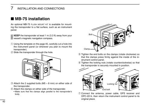
■ MB-75 installation<br />
An optional MB-75 flush mount kit is available for mounting<br />
the transponder to a flat surface, such as an instrument<br />
panel.<br />
KEEP the transponder at least 1 m (3.3 ft) away from your<br />
vessel’s magnetic navigation compass.<br />
Bolt<br />
r<br />
q Using the template on the page 45, carefully cut a hole into<br />
the instrument panel (or wherever you plan to mount the<br />
transponder).<br />
w Slide the transponder through the hole.<br />
Clamp<br />
r<br />
t Tighten the end bolts on the clamps (rotate clockwise) so<br />
that the clamps press firmly against the inside of the instrument<br />
control panel.<br />
y Tighten the locking nuts (rotate counterclockwise) so that<br />
the transponder is securely mounted in position.<br />
y<br />
40<br />
e Attach the 2 supplied bolts (M5 × 8 mm) on either side of<br />
the transponder.<br />
r Attach the clamps on either side of the transponder.<br />
• Make sure that the clamps align parallel to the transponder’s<br />
body.<br />
t<br />
End bolt<br />
Locking nut<br />
u Connect the antenna, power cable, GPS receiver and<br />
OPC-2014, then return the instrument control panel to its<br />
original place.