MA-500TR Instruction Manual - ICOM Canada
MA-500TR Instruction Manual - ICOM Canada
MA-500TR Instruction Manual - ICOM Canada

Create successful ePaper yourself
Turn your PDF publications into a flip-book with our unique Google optimized e-Paper software.
INSTALLATION AND CONNECTIONS<br />
7<br />
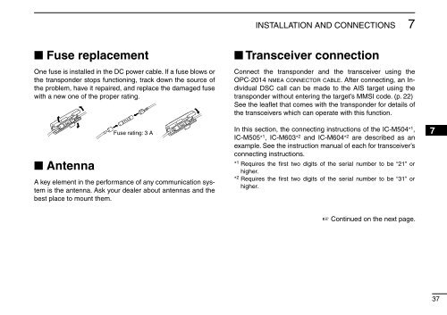
■ Fuse replacement<br />
One fuse is installed in the DC power cable. If a fuse blows or<br />
the transponder stops functioning, track down the source of<br />
the problem, have it repaired, and replace the damaged fuse<br />
with a new one of the proper rating.<br />
■ Antenna<br />
Fuse rating: 3 A<br />
A key element in the performance of any communication system<br />
is the antenna. Ask your dealer about antennas and the<br />
best place to mount them.<br />
■ Transceiver connection<br />
Connect the transponder and the transceiver using the<br />
OPC-2014 nmea connector cable. After connecting, an Individual<br />
DSC call can be made to the AIS target using the<br />
transponder without entering the target’s MMSI code. (p. 22)<br />
See the leaflet that comes with the transponder for details of<br />
the transceivers which can operate with this function.<br />
In this section, the connecting instructions of the IC-M504* 1 ,<br />
IC-M505* 1 , IC-M603* 2 and IC-M604* 2 are described as an<br />
example. See the instruction manual of each for transceiver’s<br />
connecting instructions.<br />
* 1 Requires the first two digits of the serial number to be “21” or<br />
higher.<br />
* 2 Requires the first two digits of the serial number to be “31” or<br />
higher.<br />
☞ Continued on the next page.<br />
1<br />
2<br />
3<br />
4<br />
5<br />
6<br />
7<br />
8<br />
9<br />
10<br />
11<br />
12<br />
13<br />
14<br />
15<br />
16<br />
37