

Predictive Control of Three Phase AC/DC Converters
Predictive Control of Three Phase AC/DC Converters
Predictive Control of Three Phase AC/DC Converters

You also want an ePaper? Increase the reach of your titles
YUMPU automatically turns print PDFs into web optimized ePapers that Google loves.
ILd 1 sL+RSd - U<strong>DC</strong>UPd ULd<br />
iload ic<br />
14 CHAPTER 2. VOLTAGE SOURCE CONVERTER<br />
U Lβ = L dI Lβ<br />
dt<br />
+ RI Lβ + U P β (2.16)<br />
C dU <strong>DC</strong><br />
= 3 dt 2 (I LαS α + I Lβ S β ) − i load (2.17)<br />
Equations (2.15)–(2.17) can be represented as a block diagram in stationary<br />
coordinates as shown in Fig. 2.8.<br />
2.2.3 VSC Model in Rotating Coordinates<br />
Model in stationary coordinates presented in previous subsection, can be transformed<br />
into a two phase model in synchronously rotating dq (App. A.2) coordinates.<br />
After transformation, VSC model can be described as:<br />
U Ldq = L dI Ldq<br />
dt<br />
+ RI Ldq + U P dq + jω L LI Ldq (2.18)<br />
C dU <strong>DC</strong><br />
= 3 dt 2 R ( I Ldq S ∗ dq)<br />
− iload (2.19)<br />
where: U Ldq , I Ldq , U P dq , S dq are space vectors in rotating dq coordinates. Note<br />
that, after transformation additional block appears in (2.18), where ω L is angular<br />
frequency <strong>of</strong> line voltage.<br />
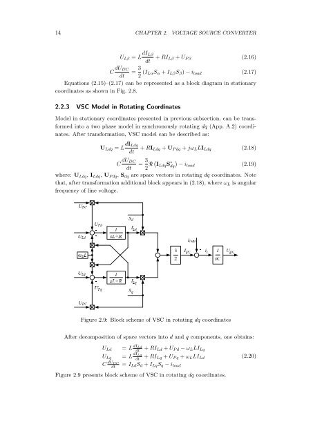
After decomposition <strong>of</strong> space vectors into d and q components, one obtains:<br />
1 sL+R ILq - U<strong>DC</strong>UPq ULq<br />
1 sCU<strong>DC</strong> - ωLL -<br />
Figure 2.9: Block scheme <strong>of</strong> VSC in rotating dq coordinates<br />
32I<strong>DC</strong><br />
U Ld<br />
+ RI Ld + U P d − ω L LI Lq<br />
= L dI Lq<br />
dt<br />
+ RI Lq + U P q + ω L LI Ld<br />
(2.20)<br />
dt<br />
= I Ld S d + I Lq S q − i load<br />
U Lq<br />
C dU <strong>DC</strong><br />
= L dI Ld<br />
dt<br />
Sq<br />
Figure 2.9 presents block scheme <strong>of</strong> VSC in rotating dq coordinates.


![[TCP] Opis układu - Instytut Sterowania i Elektroniki Przemysłowej ...](https://img.yumpu.com/23535443/1/184x260/tcp-opis-ukladu-instytut-sterowania-i-elektroniki-przemyslowej-.jpg?quality=85)
