

Predictive Control of Three Phase AC/DC Converters
Predictive Control of Three Phase AC/DC Converters
Predictive Control of Three Phase AC/DC Converters

Create successful ePaper yourself
Turn your PDF publications into a flip-book with our unique Google optimized e-Paper software.
3.2. VOLTAGE ORIENTED CONTROL 19<br />
rejection performance in transient states. Equations (3.1) and (3.2) describe PI<br />
controller proportional gain K C and its time constant T IC :<br />
K C =<br />
T RL<br />
2τ t K RL<br />
(3.1)<br />
T IC = 4τ t (3.2)<br />
where: T RL = L R , K RL = 1 R<br />
is time constant and gain <strong>of</strong> choke mathematical<br />
model respectively, and τ t is sum <strong>of</strong> the small time constants defined as:<br />
τ t = T s + T P W M (3.3)<br />
where: T s is sampling time, and T P W M = 1 2 T s is PWM generation time delay.<br />
Figure 3.3 shows block diagram <strong>of</strong> active current control loop, where τ 0 is<br />
transistors dead time.<br />
U Ldist<br />
I dref<br />
I dreff I Lderr K C (sT IC +1) U dref K VSC e -sτ 0<br />
1<br />
K RL I Ld<br />
sT fC +1<br />
Prefilter<br />
-<br />
I Ld<br />
sT IC<br />
sτ t +1<br />
sT RL +1<br />
PI S&H, VSC Input Choke<br />
-<br />
Figure 3.3: Block diagram <strong>of</strong> active current I Ld control loop in synchronous<br />
rotating reference coordinates with prefilter<br />
(a)<br />
Step Response<br />
(b)<br />
Step Response<br />
1.5<br />
From: I dref<br />
To: I d<br />
1.5<br />
From: I dref<br />
To: I d<br />
System: dq_PI_c_1<br />
I/O: I_{dref} to I_{d}<br />
Peak amplitude: 1.41<br />
Overshoot (%): 41.1<br />
At time (sec): 0.000849<br />
System: dq_PI_c_1<br />
I/O: I_{dref} to I_{d}<br />
Peak amplitude: 1.07<br />
Overshoot (%): 7.19<br />
At time (sec): 0.00148<br />
1<br />
1<br />
Amplitude<br />
0.5<br />
System: dq_PI_c_1<br />
I/O: I_{dref} to I_{d}<br />
Rise Time (sec): 0.000316<br />
System: dq_PI_c_1<br />
I/O: I_{dref} to I_{d}<br />
Settling Time (sec): 0.00247<br />
Amplitude<br />
0.5<br />
System: dq_PI_c_1<br />
I/O: I_{dref} to I_{d}<br />
Rise Time (sec): 0.000699<br />
System: dq_PI_c_1<br />
I/O: I_{dref} to I_{d}<br />
Settling Time (sec): 0.00201<br />
0<br />
0 0.5 1 1.5 2 2.5 3 3.5<br />
Time (sec)<br />
x 10 −3<br />
0<br />
0 0.5 1 1.5 2 2.5 3 3.5<br />
Time (sec)<br />
x 10 −3<br />
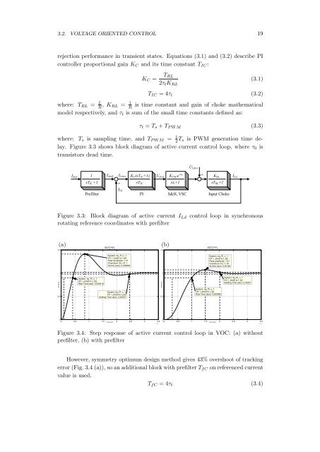
Figure 3.4: Step response <strong>of</strong> active current control loop in VOC: (a) without<br />
prefilter, (b) with prefilter<br />
However, symmetry optimum design method gives 43% overshoot <strong>of</strong> tracking<br />
error (Fig. 3.4 (a)), so an additional block with prefilter T fC on referenced current<br />
value is used.<br />
T fC = 4τ t (3.4)


![[TCP] Opis układu - Instytut Sterowania i Elektroniki Przemysłowej ...](https://img.yumpu.com/23535443/1/184x260/tcp-opis-ukladu-instytut-sterowania-i-elektroniki-przemyslowej-.jpg?quality=85)
