

Predictive Control of Three Phase AC/DC Converters
Predictive Control of Three Phase AC/DC Converters
Predictive Control of Three Phase AC/DC Converters

Create successful ePaper yourself
Turn your PDF publications into a flip-book with our unique Google optimized e-Paper software.
4 Sector 5Sector Sector 2<br />
7 Sector 8Sector Sector 5<br />
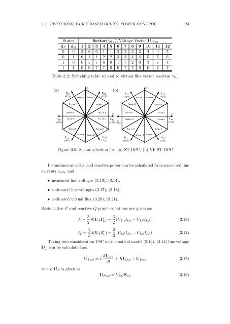
3.3. SWITCHING TABLE BASED DIRECT POWER CONTROL 23<br />
States Sector(γ ΨL )/Voltage Vector U P (n)<br />
d P d Q 1 2 3 4 5 6 7 8 9 10 11 12<br />
0 0 5 6 6 1 1 2 2 3 3 4 4 5<br />
0 1 6 1 1 2 2 3 3 4 4 5 5 6<br />
1 0 0 5 7 6 0 1 7 2 0 3 7 4<br />
1 1 0 0 7 7 0 0 7 7 0 0 7 7<br />
Table 3.2: Switching table related to virtual flux vector position γ ΨL<br />
(a)<br />
β<br />
(010)<br />
UP3<br />
Sector 3<br />
(b)<br />
β<br />
(110)<br />
UP2<br />
(010)<br />
UP3<br />
Sector 6<br />
(110)<br />
UP2<br />
α<br />
α<br />
(011)<br />
UP4<br />
(100)<br />
UP4 UP1<br />
(011)<br />
(100)<br />
UP1<br />
(001)<br />
6 Sector 7<br />
UP5<br />
(101)<br />
1 Sector 12<br />
UP6<br />
Sector 8Sector 9 Sector 10Sector 11<br />
(001)<br />
9 Sector 10<br />
UP5<br />
Sector 11Sector 12Sector 1Sector 2<br />
(101)<br />
4 Sector 3<br />
UP6<br />
Figure 3.9: Sector selection for: (a) ST-DPC, (b) VF-ST-DPC<br />
Instantaneous active and reactive power can be calculated from measured line<br />
currents i Labc and:<br />
• measured line voltages (3.13), (3.14),<br />
• estimated line voltages (3.17), (3.18),<br />
• estimated virtual flux (3.20), (3.21).<br />
Basic active P and reactive Q power equations are given as:<br />
P = 3 2 R(U LI ∗ L) = 3 2 (U LαI Lα + U Lβ I Lβ ) (3.13)<br />
Q = 3 2 I(U LI ∗ L) = 3 2 (U LβI Lα − U Lα I Lβ ) (3.14)<br />
Taking into consideration VSC mathematical model (2.13), (2.14) line voltage<br />
U L can be calculated as:<br />
where U P is given as:<br />
U Lαβ = L dI Lαβ<br />
dt<br />
+ RI Lαβ + U P αβ (3.15)<br />
U P αβ = U <strong>DC</strong> S αβ (3.16)


![[TCP] Opis układu - Instytut Sterowania i Elektroniki Przemysłowej ...](https://img.yumpu.com/23535443/1/184x260/tcp-opis-ukladu-instytut-sterowania-i-elektroniki-przemyslowej-.jpg?quality=85)
