Oil and Gas at Your Door? (2005 Edition) - Earthworks
Oil and Gas at Your Door? (2005 Edition) - Earthworks
Oil and Gas at Your Door? (2005 Edition) - Earthworks

You also want an ePaper? Increase the reach of your titles
YUMPU automatically turns print PDFs into web optimized ePapers that Google loves.
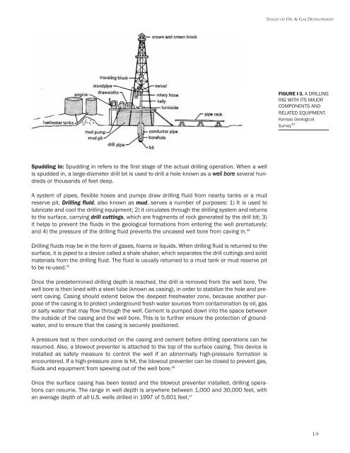
STAGES OF OIL & GAS DEVELOPMENT<br />
FIGURE I-3. A DRILLING<br />
RIG WITH ITS MAJOR<br />
COMPONENTS AND<br />
RELATED EQUIPMENT.<br />
Kansas Geological<br />
Survey 43<br />
Spudding in: Spudding in refers to the first stage of the actual drilling oper<strong>at</strong>ion. When a well<br />
is spudded in, a large-diameter drill bit is used to drill a hole known as a well bore several hundreds<br />
or thous<strong>and</strong>s of feet deep.<br />
A system of pipes, flexible hoses <strong>and</strong> pumps draw drilling fluid from nearby tanks or a mud<br />
reserve pit. Drilling fluid, also known as mud, serves a number of purposes: 1) It is used to<br />
lubric<strong>at</strong>e <strong>and</strong> cool the drilling equipment; 2) it circul<strong>at</strong>es through the drilling system <strong>and</strong> returns<br />
to the surface, carrying drill cuttings, which are fragments of rock gener<strong>at</strong>ed by the drill bit; 3)<br />
it helps to prevent the fluids in the geological form<strong>at</strong>ions from entering the well prem<strong>at</strong>urely;<br />
<strong>and</strong> 4) the pressure of the drilling fluid prevents the uncased well bore from caving in. 44<br />
Drilling fluids may be in the form of gases, foams or liquids. When drilling fluid is returned to the<br />
surface, it is piped to a device called a shale shaker, which separ<strong>at</strong>es the drill cuttings <strong>and</strong> solid<br />
m<strong>at</strong>erials from the drilling fluid. The fluid is usually returned to a mud tank or mud reserve pit<br />
to be re-used. 45<br />
Once the predetermined drilling depth is reached, the drill is removed from the well bore. The<br />
well bore is then lined with a steel tube (known as casing), in order to stabilize the hole <strong>and</strong> prevent<br />
caving. Casing should extend below the deepest freshw<strong>at</strong>er zone, because another purpose<br />
of the casing is to protect underground fresh w<strong>at</strong>er sources from contamin<strong>at</strong>ion by oil, gas<br />
or salty w<strong>at</strong>er th<strong>at</strong> may flow through the well. Cement is pumped down into the space between<br />
the outside of the casing <strong>and</strong> the well bore. This is to further ensure the protection of groundw<strong>at</strong>er,<br />
<strong>and</strong> to ensure th<strong>at</strong> the casing is securely positioned.<br />
A pressure test is then conducted on the casing <strong>and</strong> cement before drilling oper<strong>at</strong>ions can be<br />
resumed. Also, a blowout preventer is <strong>at</strong>tached to the top of the surface casing. This device is<br />
installed as safety measure to control the well if an abnormally high-pressure form<strong>at</strong>ion is<br />
encountered. If a high-pressure zone is hit, the blowout preventer can be closed to prevent gas,<br />
fluids <strong>and</strong> equipment from spewing out of the well bore. 46<br />
Once the surface casing has been tested <strong>and</strong> the blowout preventer installed, drilling oper<strong>at</strong>ions<br />
can resume. The range in well depth is anywhere between 1,000 <strong>and</strong> 30,000 feet, with<br />
an average depth of all U.S. wells drilled in 1997 of 5,601 feet. 47 I-9