- Page 1 and 2:
ST1 B T2 A T1 C * B T3 page 0 ST3 T
- Page 3 and 4:
page i 1.1 TODO LIST 1.3 2. PROGRAM
- Page 5 and 6:
page iii 7.5 ASSIGNMENT PROBLEMS 7.
- Page 7 and 8:
page v 14.3 PROGRAMS 14.3 14.4 VARI
- Page 9 and 10:
page vii 20.4 PRACTICE PROBLEMS 20.
- Page 11 and 12:
page ix 25.2 CONTROL OF LOGICAL ACT
- Page 13 and 14:
page xi 30. HUMAN MACHINE INTERFACE
- Page 15 and 16:
page xiii 35.16 P 35.21 35.17 Q 35.
- Page 17 and 18:
plc wiring - 1.2 • Linear - Can b
- Page 19 and 20:
plc wiring - 1.4 - update serial IO
- Page 21 and 22:
plc wiring - 2.2 logic diagrams was
- Page 23 and 24:
plc wiring - 2.4 115VAC wall plug r
- Page 25 and 26:
plc wiring - 2.6 A B B Note: When A
- Page 27 and 28:
plc wiring - 2.8 number there. The
- Page 29 and 30:
plc wiring - 2.10 i := 0; REPEAT i
- Page 31 and 32:
plc wiring - 2.12 x Normally open,
- Page 33 and 34:
plc wiring - 2.14 Solution: There a
- Page 35 and 36:
plc wiring - 2.16 4. Less expensive
- Page 37 and 38:
plc wiring - 3.2 allows the PLC to
- Page 39 and 40:
plc wiring - 3.4 5 Vdc (TTL) 200-24
- Page 41 and 42:
plc wiring - 3.6 Remember - Don’t
- Page 43 and 44:
plc wiring - 3.8 As with input modu
- Page 45 and 46:
plc wiring - 3.10 accidentally conn
- Page 47 and 48:
plc wiring - 3.12 could have many d
- Page 49 and 50:
plc wiring - 3.14 ing large power l
- Page 51 and 52:
plc wiring - 3.16 The lines of thes
- Page 53 and 54:
plc wiring - 3.18 In the wiring dia
- Page 55 and 56:
plc wiring - 3.20 temperature norma
- Page 57 and 58:
plc wiring - 3.22 3.6 SUMMARY • P
- Page 59 and 60:
plc wiring - 3.24 show all necessar
- Page 61 and 62:
plc wiring - 3.26 12. 0 1 2 3 4 5 6
- Page 63 and 64:
plc wiring - 3.28 16. relay output
- Page 65 and 66:
discrete sensors - 4.1 4. LOGICAL S
- Page 67 and 68:
discrete sensors - 4.3 4.2.2 Transi
- Page 69 and 70:
discrete sensors - 4.5 value, and t
- Page 71 and 72:
discrete sensors - 4.7 PLC Input Ca
- Page 73 and 74:
discrete sensors - 4.9 PLC Input Ca
- Page 75 and 76:
discrete sensors - 4.11 4.3 PRESENC
- Page 77 and 78:
discrete sensors - 4.13 components,
- Page 79 and 80:
discrete sensors - 4.15 emitter obj
- Page 81 and 82:
discrete sensors - 4.17 emitter ref
- Page 83 and 84:
discrete sensors - 4.19 ure 4.22. T
- Page 85 and 86:
discrete sensors - 4.21 electrode m
- Page 87 and 88:
discrete sensors - 4.23 Material Co
- Page 89 and 90:
discrete sensors - 4.25 shielded un
- Page 91 and 92:
discrete sensors - 4.27 4.5 PRACTIC
- Page 93 and 94:
discrete sensors - 4.29 in:2.I.Data
- Page 95 and 96:
discrete sensors - 4.31 4. 24Vdc ou
- Page 97 and 98:
discrete sensors - 4.33 6. 00 01 02
- Page 99 and 100:
discrete sensors - 4.35 8. + power
- Page 101 and 102:
discrete sensors - 4.37 4. a) Show
- Page 103 and 104:
discrete actuators - 5.2 As mention
- Page 105 and 106:
discrete actuators - 5.4 Two way, t
- Page 107 and 108:
discrete actuators - 5.6 single act
- Page 109 and 110:
discrete actuators - 5.8 Figure 5.6
- Page 111 and 112:
discrete actuators - 5.10 5.8 OTHER
- Page 113 and 114:
discrete actuators - 5.12 3. ADD SO
- Page 115 and 116:
plc boolean - 6.2 Note: By conventi
- Page 117 and 118:
plc boolean - 6.4 Idempotent A + A
- Page 119 and 120:
plc boolean - 6.6 6.3 LOGIC DESIGN
- Page 121 and 122:
plc boolean - 6.8 Ladder Logic for
- Page 123 and 124:
plc boolean - 6.10 der logic there
- Page 125 and 126:
plc boolean - 6.12 A = B⋅ C⋅ (
- Page 127 and 128:
plc boolean - 6.14 A+ CA = A+ C pro
- Page 129 and 130:
plc boolean - 6.16 D1 D2 D3 multipl
- Page 131 and 132:
plc boolean - 6.18 Solution: D = A+
- Page 133 and 134:
plc boolean - 6.20 The inputs and o
- Page 135 and 136:
plc boolean - 6.22 A = ( S⋅ M⋅
- Page 137 and 138:
plc boolean - 6.24 • Truth tables
- Page 139 and 140:
plc boolean - 6.26 b) Simplify the
- Page 141 and 142:
plc boolean - 6.28 2. A B D C 3. B
- Page 143 and 144:
plc boolean - 6.30 9. a) ( A+ B)
- Page 145 and 146:
plc boolean - 6.32 A B C B C D C A
- Page 147 and 148:
plc boolean - 6.34 17. D A Y 18. CA
- Page 149 and 150:
plc boolean - 6.36 c) A X B A C C A
- Page 151 and 152:
plc boolean - 6.38 2. Simplify the
- Page 153 and 154:
plc karnaugh - 7.1 7. KARNAUGH MAPS
- Page 155 and 156:
plc karnaugh - 7.3 expression. The
- Page 157 and 158:
plc karnaugh - 7.5 7.3 PRACTICE PRO
- Page 159 and 160:
plc karnaugh - 7.7 5. Examine the t
- Page 161 and 162:
plc karnaugh - 7.9 Boolean equation
- Page 163 and 164:
plc karnaugh - 7.11 13. Consider th
- Page 165 and 166:
plc karnaugh - 7.13 5. 00 FG 01 11
- Page 167 and 168:
plc karnaugh - 7.15 9. CD AB AB A B
- Page 169 and 170:
plc karnaugh - 7.17 12. DA + ACD AB
- Page 171 and 172:
plc karnaugh - 7.19 4. Convert the
- Page 173 and 174:
plc operation - 8.2 inputs and outp
- Page 175 and 176:
plc operation - 8.4 input scan take
- Page 177 and 178:
plc operation - 8.6 8.3 PLC STATUS
- Page 179 and 180:
plc operation - 8.8 outputs are not
- Page 181 and 182:
plc timers - 9.1 9. LATCHES, TIMERS
- Page 183 and 184:
plc timers - 9.3 The operation of t
- Page 185 and 186:
plc timers - 9.5 I/0 O/0 I/0 O/1 L
- Page 187 and 188:
plc timers - 9.7 oven has been turn
- Page 189 and 190:
plc timers - 9.9 The timing diagram
- Page 191 and 192:
plc timers - 9.11 go TON t_1 delay
- Page 193 and 194:
plc timers - 9.13 Start Stop Auto A
- Page 195 and 196:
plc timers - 9.15 A CTU Counter exa
- Page 197 and 198:
plc timers - 9.17 The program in Fi
- Page 199 and 200:
plc timers - 9.19 9.6 INTERNAL BITS
- Page 201 and 202:
plc timers - 9.21 Solution: A TON P
- Page 203 and 204:
plc timers - 9.23 Solution: Motor S
- Page 205 and 206:
plc timers - 9.25 Solution: Go Stop
- Page 207 and 208:
plc timers - 9.27 Solution: TS1 LS1
- Page 209 and 210:
plc timers - 9.29 8. Complete the t
- Page 211 and 212:
plc timers - 9.31 17. Design a conv
- Page 213 and 214:
plc timers - 9.33 7. A RTF Timer t
- Page 215 and 216:
plc timers - 9.35 9. input TON RTO
- Page 217 and 218:
plc timers - 9.37 14. A delay.DN TO
- Page 219 and 220:
plc timers - 9.39 16. left_button T
- Page 221 and 222:
plc timers - 9.41 18. A T4:0/TT C5:
- Page 223 and 224:
plc timers - 9.43 22. GIVE SOLUTION
- Page 225 and 226:
plc timers - 9.45 3. Explain what w
- Page 227 and 228:
plc design - 10.2 Most control syst
- Page 229 and 230:
plc design - 10.4 Description: Step
- Page 231 and 232:
plc design - 10.6 step4 bottom LS s
- Page 233 and 234:
plc design - 10.8 Description: A ha
- Page 235 and 236:
plc design - 10.10 3. The first wra
- Page 237 and 238:
plc design - 10.12 3. (for both sol
- Page 239 and 240:
plc design - 10.14 (with latches fi
- Page 241 and 242:
plc design - 10.16 a) Start in an i
- Page 243 and 244:
plc flowchart - 11.1 11. FLOWCHART
- Page 245 and 246:
plc flowchart - 11.3 START Open out
- Page 247 and 248:
plc flowchart - 11.5 STEP 1: Add la
- Page 249 and 250:
plc flowchart - 11.7 STEP 2: Write
- Page 251 and 252:
plc flowchart - 11.9 F2 start MCR U
- Page 253 and 254:
plc flowchart - 11.11 F6 MCR L outl
- Page 255 and 256:
plc flowchart - 11.13 FS F1 F6 T1 T
- Page 257 and 258:
plc flowchart - 11.15 11.4 SUMMARY
- Page 259 and 260:
plc flowchart - 11.17 2. Start Get
- Page 261 and 262:
plc flowchart - 11.19 F3 gas can fu
- Page 263 and 264:
plc flowchart - 11.21 first scan L
- Page 265 and 266:
plc flowchart - 11.23 ST3 button re
- Page 267 and 268:
plc flowchart - 11.25 ST8 button re
- Page 269 and 270:
plc flowchart - 11.27 3. A welding
- Page 271 and 272:
plc states - 12.1 12. STATE BASED D
- Page 273 and 274:
plc states - 12.3 be active while c
- Page 275 and 276:
plc states - 12.5 Red Yellow Green
- Page 277 and 278:
plc states - 12.7 Step 2: Define St
- Page 279 and 280:
plc states - 12.9 RESET THE STATES
- Page 281 and 282:
plc states - 12.11 FIRST STATE WAIT
- Page 283 and 284:
plc states - 12.13 FOURTH STATE WAI
- Page 285 and 286:
plc states - 12.15 first scan L STB
- Page 287 and 288:
plc states - 12.17 Informally, Stat
- Page 289 and 290:
plc states - 12.19 Now, simplify th
- Page 291 and 292:
plc states - 12.21 OUTPUT LOGIC FOR
- Page 293 and 294:
plc states - 12.23 Each of the alte
- Page 295 and 296:
plc states - 12.25 A state diagram
- Page 297 and 298:
plc states - 12.27 CALCULATE STATE
- Page 299 and 300:
plc states - 12.29 STA T5 B T4 D ST
- Page 301 and 302:
plc states - 12.31 4. Given the fol
- Page 303 and 304:
plc states - 12.33 24 V AC Power Su
- Page 305 and 306:
plc states - 12.35 3. T1 T2 = ST1
- Page 307 and 308:
plc states - 12.37 5. TA TB TC TD T
- Page 309 and 310:
plc states - 12.39 first scan MCR L
- Page 311 and 312:
plc states - 12.41 state 3 MCR rese
- Page 313 and 314:
plc states - 12.43 FS L state_1 U s
- Page 315 and 316:
plc states - 12.45 state_4 MCR remo
- Page 317 and 318:
plc states - 12.47 ST1 remote T1 bu
- Page 319 and 320:
plc states - 12.49 12.5 ASSIGNMENT
- Page 321 and 322:
plc states - 12.51 6. Implement the
- Page 323 and 324:
plc states - 12.53 using an equatio
- Page 325 and 326:
plc states - 12.55 INPUTS I/1 - sta
- Page 327 and 328:
plc numbers - 13.2 decimal binary o
- Page 329 and 330:
plc numbers - 13.4 start with decim
- Page 331 and 332:
plc numbers - 13.6 There are three
- Page 333 and 334:
plc numbers - 13.8 decimal binary b
- Page 335 and 336:
plc numbers - 13.10 13.2.2 Other Ba
- Page 337 and 338:
plc numbers - 13.12 Figure 13.17 AS
- Page 339 and 340:
plc numbers - 13.14 An example of a
- Page 341 and 342:
plc numbers - 13.16 DATA 124 43 255
- Page 343 and 344:
plc numbers - 13.18 a) from base 10
- Page 345 and 346:
plc numbers - 13.20 17. Do the foll
- Page 347 and 348:
plc numbers - 13.22 14. octal binar
- Page 349 and 350:
plc memory - 14.1 14. PLC MEMORY To
- Page 351 and 352:
plc memory - 14.3 14.3 PROGRAMS The
- Page 353 and 354:
plc memory - 14.5 8 - an integer 8.
- Page 355 and 356:
plc memory - 14.7 CU - count up bit
- Page 357 and 358:
plc memory - 14.9 Immediately acces
- Page 359 and 360:
plc memory - 14.11 A selected list
- Page 361 and 362:
plc memory - 14.13 onds after it ha
- Page 363 and 364:
plc memory - 14.15 10. first scan R
- Page 365 and 366:
plc basic functions - 15.2 Combinat
- Page 367 and 368:
plc basic functions - 15.4 A MOV So
- Page 369 and 370:
plc basic functions - 15.6 store th
- Page 371 and 372:
plc basic functions - 15.8 ACS(valu
- Page 373 and 374:
plc basic functions - 15.10 go CPT
- Page 375 and 376:
plc basic functions - 15.12 15.2.4.
- Page 377 and 378:
plc basic functions - 15.14 copy an
- Page 379 and 380:
plc basic functions - 15.16 EQU A B
- Page 381 and 382:
plc basic functions - 15.18 CMP exp
- Page 383 and 384:
plc basic functions - 15.20 Figure
- Page 385 and 386:
plc basic functions - 15.22 after a
- Page 387 and 388:
plc basic functions - 15.24 As desi
- Page 389 and 390:
plc basic functions - 15.26 • Val
- Page 391 and 392:
plc basic functions - 15.28 15.7 PR
- Page 393 and 394:
plc basic functions - 15.30 5. addr
- Page 395 and 396:
plc basic functions - 15.32 S2 part
- Page 397 and 398:
plc basic functions - 15.34 11. AND
- Page 399 and 400:
plc advanced functions - 16.1 16. A
- Page 401 and 402:
plc advanced functions - 16.3 Arith
- Page 403 and 404:
plc advanced functions - 16.5 A FFL
- Page 405 and 406:
plc advanced functions - 16.7 A SQO
- Page 407 and 408:
plc advanced functions - 16.9 A B C
- Page 409 and 410:
plc advanced functions - 16.11 Main
- Page 411 and 412:
plc advanced functions - 16.13 A B
- Page 413 and 414:
plc advanced functions - 16.15 Main
- Page 415 and 416:
plc advanced functions - 16.17 A X
- Page 417 and 418:
plc advanced functions - 16.19 e.g.
- Page 419 and 420:
plc advanced functions - 16.21 S:FS
- Page 421 and 422:
plc advanced functions - 16.23 STA
- Page 423 and 424:
plc advanced functions - 16.25 16.6
- Page 425 and 426:
plc advanced functions - 16.27 4. W
- Page 427 and 428:
plc advanced functions - 16.29 b[0]
- Page 429 and 430:
plc advanced functions - 16.31 3. a
- Page 431 and 432:
plc advanced functions - 16.33 S3 S
- Page 433 and 434:
plc advanced functions - 16.35 10.
- Page 435 and 436:
plc advanced functions - 16.37 16.1
- Page 437 and 438:
plc iec61131 - 17.1 17. OPEN CONTRO
- Page 439 and 440:
plc iec61131 - 17.3 Name Type Bits
- Page 441 and 442:
plc iec61131 - 17.5 technique.) i)
- Page 443 and 444:
plc il - 18.2 I:000/00 I:000/01 O:0
- Page 445 and 446:
plc il - 18.4 Operator Modifiers Da
- Page 447 and 448:
plc il - 18.6 mally using the MPS,
- Page 449 and 450:
plc il - 18.8 value. I:001/0 TON Ti
- Page 451 and 452:
plc il - 18.10 • The Allen Bradle
- Page 453 and 454:
plc st - 19.2 PROGRAM main VAR i :
- Page 455 and 456:
plc st - 19.4 When defining variabl
- Page 457 and 458:
plc st - 19.6 Character strings def
- Page 459 and 460:
plc st - 19.8 AND(A,B) OR(A,B) XOR(
- Page 461 and 462:
plc st - 19.10 The example in Figur
- Page 463 and 464:
plc st - 19.12 Function ABS(A); ACO
- Page 465 and 466:
plc st - 19.14 .... D := TEST(1.3,
- Page 467 and 468:
plc st - 19.16 19.4 SUMMARY • Str
- Page 469 and 470:
plc sfc - 20.1 20. SEQUENTIAL FUNCT
- Page 471 and 472:
plc sfc - 20.3 selection branch - a
- Page 473 and 474:
plc sfc - 20.5 press will then retr
- Page 475 and 476:
plc sfc - 20.7 first scan INITIALIZ
- Page 477 and 478:
plc sfc - 20.9 transition 5 top lim
- Page 479 and 480:
plc sfc - 20.11 step 6 U step 6 L t
- Page 481 and 482:
plc sfc - 20.13 Program 3 (for step
- Page 483 and 484:
plc sfc - 20.15 ST2 TR8 ST2 TR13 FS
- Page 485 and 486:
plc sfc - 20.17 20.4 PRACTICE PROBL
- Page 487 and 488:
plc sfc - 20.19 2. Start EW crosswa
- Page 489 and 490:
plc sfc - 20.21 4. step 1 step 2 T1
- Page 491 and 492:
plc sfc - 20.23 T1 remote L step 3
- Page 493 and 494:
plc sfc - 20.25 step 1 step 2 step
- Page 495 and 496:
plc fb - 21.2 A FBD program is cons
- Page 497 and 498:
plc fb - 21.4 Figure 21.6 shows a d
- Page 499 and 500:
plc analog - 22.1 22. ANALOG INPUTS
- Page 501 and 502:
plc analog - 22.3 A more realistic
- Page 503 and 504:
plc analog - 22.5 R = 2 N = R max -
- Page 505 and 506:
plc analog - 22.7 Figure 22.6 Low S
- Page 507 and 508:
plc analog - 22.9 ASIDE: This devic
- Page 509 and 510:
plc analog - 22.11 (Note: each type
- Page 511 and 512:
plc analog - 22.13 important if the
- Page 513 and 514:
plc analog - 22.15 Given, N = 8, R
- Page 515 and 516:
plc analog - 22.17 tion will change
- Page 517 and 518:
plc analog - 22.19 A t V eff = A A
- Page 519 and 520:
plc analog - 22.21 flow. The resist
- Page 521 and 522:
plc analog - 22.23 • Analog shiel
- Page 523 and 524:
plc analog - 22.25 5. A card with a
- Page 525 and 526:
plc analog - 22.27 7. A SIN Source
- Page 527 and 528:
plc analog - 22.29 22.8 ASSIGNMENT
- Page 529 and 530:
continuous sensors - 23.2 terized w
- Page 531 and 532:
continuous sensors - 23.4 θ max θ
- Page 533 and 534:
continuous sensors - 23.6 sensors r
- Page 535 and 536:
continuous sensors - 23.8 Normally
- Page 537 and 538:
continuous sensors - 23.10 A rod dr
- Page 539 and 540:
continuous sensors - 23.12 on off o
- Page 541 and 542:
continuous sensors - 23.14 Sealant
- Page 543 and 544:
continuous sensors - 23.16 After th
- Page 545 and 546:
continuous sensors - 23.18 stress d
- Page 547 and 548:
continuous sensors - 23.20 23.2.5 L
- Page 549 and 550:
continuous sensors - 23.22 These se
- Page 551 and 552:
continuous sensors - 23.24 result i
- Page 553 and 554:
continuous sensors - 23.26 very hig
- Page 555 and 556:
continuous sensors - 23.28 mV 80 E
- Page 557 and 558:
continuous sensors - 23.30 Thermist
- Page 559 and 560:
continuous sensors - 23.32 23.2.9 O
- Page 561 and 562:
continuous sensors - 23.34 The circ
- Page 563 and 564:
continuous sensors - 23.36 put is p
- Page 565 and 566:
continuous sensors - 23.38 ratio. I
- Page 567 and 568:
continuous sensors - 23.40 10. enco
- Page 569 and 570:
continuous actuators - 24.1 24. CON
- Page 571 and 572:
continuous actuators - 24.3 command
- Page 573 and 574:
continuous actuators - 24.5 wear, w
- Page 575 and 576:
continuous actuators - 24.7 ASIDE:
- Page 577 and 578:
continuous actuators - 24.9 L2 L1 L
- Page 579 and 580:
continuous actuators - 24.11 torque
- Page 581 and 582:
continuous actuators - 24.13 • Si
- Page 583 and 584:
continuous actuators - 24.15 runnin
- Page 585 and 586:
continuous actuators - 24.17 torque
- Page 587 and 588:
continuous actuators - 24.19 torque
- Page 589 and 590:
continuous actuators - 24.21 cally
- Page 591 and 592:
continuous actuators - 24.23 e f =
- Page 593 and 594:
continuous actuators - 24.25 24.5 S
- Page 595 and 596:
continuous actuators - 24.27 a) (an
- Page 597 and 598:
plc pid - 25.2 valve a) Water Tank
- Page 599 and 600:
plc pid - 25.4 to a process, and tu
- Page 601 and 602:
plc pid - 25.6 θ neural desired +
- Page 603 and 604:
plc pid - 25.8 next two sections de
- Page 605 and 606:
plc pid - 25.10 Figure 25.10 A Comb
- Page 607 and 608:
plc pid - 25.12 25.3.4 PID Control
- Page 609 and 610:
plc pid - 25.14 PID Control Block:
- Page 611 and 612:
plc pid - 25.16 S2:1/15 - first sca
- Page 613 and 614:
plc pid - 25.18 SOLUTION Analog Inp
- Page 615 and 616:
plc pid - 25.20 BT9:0/DN BT9:2/EN B
- Page 617 and 618:
plc pid - 25.22 25.7 PRACTICE PROBL
- Page 619 and 620:
plc pid - 25.24 7. S2:1/15 - first
- Page 621 and 622:
plc pid - 25.26 25.8 ASSIGNMENT PRO
- Page 623 and 624:
plc fuzzy - 26.1 26. FUZZY LOGIC T
- Page 625 and 626:
plc fuzzy - 26.3 1. If (bucket is f
- Page 627 and 628:
plc fuzzy - 26.5 1. If v error is L
- Page 629 and 630:
plc fuzzy - 26.7 final motor contro
- Page 631 and 632:
plc fuzzy - 26.9 response will be s
- Page 633 and 634:
plc serial - 27.2 An example of a n
- Page 635 and 636:
plc serial - 27.4 A typical data by
- Page 637 and 638:
plc serial - 27.6 Modem Computer co
- Page 639 and 640:
plc serial - 27.8 RI - (ring indica
- Page 641 and 642:
plc serial - 27.10 ABL(channel, con
- Page 643 and 644:
plc serial - 27.12 ACI String ST9:1
- Page 645 and 646:
plc serial - 27.14 on many new inst
- Page 647 and 648:
plc serial - 27.16 5. Write a progr
- Page 649 and 650:
plc serial - 27.18 5. MOV Source F8
- Page 651 and 652:
plc network - 28.1 28. NETWORKING
- Page 653 and 654:
plc network - 28.3 ... R Repeater R
- Page 655 and 656:
plc network - 28.5 that syntax, for
- Page 657 and 658:
plc network - 28.7 28.1.4 Control N
- Page 659 and 660:
plc network - 28.9 • Data packet
- Page 661 and 662:
plc network - 28.11 MG9:0/EN MSG Se
- Page 663 and 664:
plc network - 28.13 1 bit 11 bits 1
- Page 665 and 666:
plc network - 28.15 46 to 1500 byte
- Page 667 and 668:
plc network - 28.17 1 byte 1 byte D
- Page 669 and 670:
plc network - 28.19 CMD 00 01 02 05
- Page 671 and 672:
plc network - 28.21 Table 1: Networ
- Page 673 and 674:
plc network - 28.23 Figure 28.17 A
- Page 675 and 676:
plc network - 28.25 2. MG9:0/EN MG9
- Page 677 and 678:
plc network - 28.27 b) MG9:0/EN MSG
- Page 679 and 680:
plc network - 28.29 to advance a he
- Page 681 and 682:
plc internet - 29.2 Aside: Open a D
- Page 683 and 684:
plc internet - 29.4 SMTP (Simple Ma
- Page 685 and 686:
plc internet - 29.6 Aside: While lo
- Page 687 and 688:
plc internet - 29.8 • A client do
- Page 689 and 690:
plc internet - 29.10 Windows machin
- Page 691 and 692:
plc hmi - 30.1 30. HUMAN MACHINE IN
- Page 693 and 694:
plc hmi - 30.3 1. Who needs what in
- Page 695 and 696:
plc electrical - 31.1 31. ELECTRICA
- Page 697 and 698:
plc electrical - 31.3 terminals pow
- Page 699 and 700:
plc electrical - 31.5 L1 L2 L3 star
- Page 701 and 702:
plc electrical - 31.7 L1 L2 L3 M M
- Page 703 and 704: plc electrical - 31.9 31.2.2 Ground
- Page 705 and 706: plc electrical - 31.11 Note: Always
- Page 707 and 708: plc electrical - 31.13 31.2.4 Suppr
- Page 709 and 710: plc electrical - 31.15 Dirt - Dust
- Page 711 and 712: plc electrical - 31.17 more sensiti
- Page 713 and 714: plc electrical - 31.19 • Use NO b
- Page 715 and 716: plc electrical - 31.21 4. Why are n
- Page 717 and 718: plc software - 32.2 Sabotage - For
- Page 719 and 720: plc software - 32.4 provides good t
- Page 721 and 722: plc software - 32.6 Table 1: ANSI/I
- Page 723 and 724: plc software - 32.8 orifice plate m
- Page 725 and 726: plc software - 32.10 Each block in
- Page 727 and 728: plc software - 32.12 2. A basic mod
- Page 729 and 730: plc software - 32.14 Project Notes
- Page 731 and 732: plc software - 32.16 Application No
- Page 733 and 734: plc software - 32.18 Internal Locat
- Page 735 and 736: plc software - 32.20 These design s
- Page 737 and 738: plc software - 32.22 ures to the to
- Page 739 and 740: plc software - 32.24 2. When should
- Page 741 and 742: plc selection - 33.2 • Determine
- Page 743 and 744: plc selection - 33.4 PLC MEMORY TIM
- Page 745 and 746: plc selection - 33.6 Typical values
- Page 747 and 748: plc selection - 33.8 ized programmi
- Page 749 and 750: plc selection - 33.10 33.4 PRACTICE
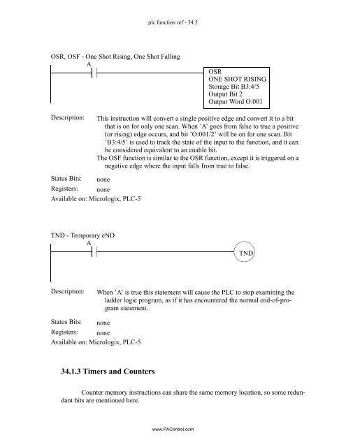
- Page 751 and 752: plc function ref - 34.2 IIN, IOT -
- Page 753: plc function ref - 34.4 MCR - Maste
- Page 757 and 758: plc function ref - 34.8 TOF - Timer
- Page 759 and 760: plc function ref - 34.10 RTO - Rete
- Page 761 and 762: plc function ref - 34.12 FBC, DDT -
- Page 763 and 764: plc function ref - 34.14 34.1.5 Cal
- Page 765 and 766: plc function ref - 34.16 AVE, STD -
- Page 767 and 768: plc function ref - 34.18 FRD, TOD,
- Page 769 and 770: plc function ref - 34.20 34.1.6 Log
- Page 771 and 772: plc function ref - 34.22 MVM - MoVe
- Page 773 and 774: plc function ref - 34.24 FAL - File
- Page 775 and 776: plc function ref - 34.26 FSC - File
- Page 777 and 778: plc function ref - 34.28 FFL, FFU,
- Page 779 and 780: plc function ref - 34.30 SQO - SeQu
- Page 781 and 782: plc function ref - 34.32 JSR/SBR/RE
- Page 783 and 784: plc function ref - 34.34 34.1.11 Ad
- Page 785 and 786: plc function ref - 34.36 PID - Prop
- Page 787 and 788: plc function ref - 34.38 ACI, AIC -
- Page 789 and 790: plc function ref - 34.40 ARD, ARL -
- Page 791 and 792: plc function ref - 34.42 AWT, AWA -
- Page 793 and 794: plc function ref - 34.44 Table 1: I
- Page 795 and 796: plc function ref - 34.46 Table 1: I
- Page 797 and 798: plc function ref - 34.48 Table 1: I
- Page 799 and 800: plc glossary - 35.2 analysis - the
- Page 801 and 802: plc glossary - 35.4 decimal(base 10
- Page 803 and 804: plc glossary - 35.6 CAD (Computer A
- Page 805 and 806:
plc glossary - 35.8 intermittent no
- Page 807 and 808:
plc glossary - 35.10 geometric dime
- Page 809 and 810:
plc glossary - 35.12 EPROM (Erasabl
- Page 811 and 812:
plc glossary - 35.14 ground - a bur
- Page 813 and 814:
plc glossary - 35.16 IOR (Inclusive
- Page 815 and 816:
plc glossary - 35.18 pneumatic syst
- Page 817 and 818:
plc glossary - 35.20 nonpositive di
- Page 819 and 820:
plc glossary - 35.22 photon - a sin
- Page 821 and 822:
plc glossary - 35.24 after a US fed
- Page 823 and 824:
plc glossary - 35.26 manufacturabil
- Page 825 and 826:
plc glossary - 35.28 time-proportio
- Page 827 and 828:
plc glossary - 35.30 it assumes the
- Page 829 and 830:
plc references - 36.2 USA. Telemech
- Page 831 and 832:
plc references - 36.4 Second Editio
- Page 833 and 834:
gfdl - 37.1 37. GNU Free Documentat
- Page 835 and 836:
gfdl - 37.3 cially, provided that t
- Page 837 and 838:
gfdl - 37.5 Sections in the Modifie
- Page 839:
gfdl - 37.7 tion License from time