

Control and Design of Microgrid Components - Power Systems ...
Control and Design of Microgrid Components - Power Systems ...
Control and Design of Microgrid Components - Power Systems ...

You also want an ePaper? Increase the reach of your titles
YUMPU automatically turns print PDFs into web optimized ePapers that Google loves.
needs <strong>of</strong> power. This solution would solve this problem <strong>and</strong> the grid would see a constant power<br />
dem<strong>and</strong> from the microgrid.<br />
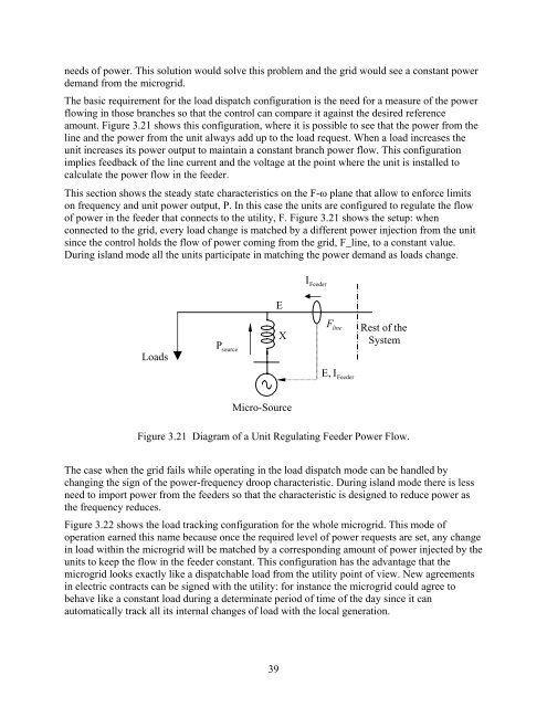
The basic requirement for the load dispatch configuration is the need for a measure <strong>of</strong> the power<br />
flowing in those branches so that the control can compare it against the desired reference<br />
amount. Figure 3.21 shows this configuration, where it is possible to see that the power from the<br />
line <strong>and</strong> the power from the unit always add up to the load request. When a load increases the<br />
unit increases its power output to maintain a constant branch power flow. This configuration<br />
implies feedback <strong>of</strong> the line current <strong>and</strong> the voltage at the point where the unit is installed to<br />
calculate the power flow in the feeder.<br />
This section shows the steady state characteristics on the F-ω plane that allow to enforce limits<br />
on frequency <strong>and</strong> unit power output, P. In this case the units are configured to regulate the flow<br />
<strong>of</strong> power in the feeder that connects to the utility, F. Figure 3.21 shows the setup: when<br />
connected to the grid, every load change is matched by a different power injection from the unit<br />
since the control holds the flow <strong>of</strong> power coming from the grid, F_line, to a constant value.<br />
During isl<strong>and</strong> mode all the units participate in matching the power dem<strong>and</strong> as loads change.<br />
I<br />
Feeder<br />
E<br />
Loads<br />
P<br />
source<br />
X<br />
F<br />
line<br />
E , I Feeder<br />
Rest <strong>of</strong> the<br />
System<br />
Micro-Source<br />
Figure 3.21 Diagram <strong>of</strong> a Unit Regulating Feeder <strong>Power</strong> Flow.<br />
The case when the grid fails while operating in the load dispatch mode can be h<strong>and</strong>led by<br />
changing the sign <strong>of</strong> the power-frequency droop characteristic. During isl<strong>and</strong> mode there is less<br />
need to import power from the feeders so that the characteristic is designed to reduce power as<br />
the frequency reduces.<br />
Figure 3.22 shows the load tracking configuration for the whole microgrid. This mode <strong>of</strong><br />
operation earned this name because once the required level <strong>of</strong> power requests are set, any change<br />
in load within the microgrid will be matched by a corresponding amount <strong>of</strong> power injected by the<br />
units to keep the flow in the feeder constant. This configuration has the advantage that the<br />
microgrid looks exactly like a dispatchable load from the utility point <strong>of</strong> view. New agreements<br />
in electric contracts can be signed with the utility: for instance the microgrid could agree to<br />
behave like a constant load during a determinate period <strong>of</strong> time <strong>of</strong> the day since it can<br />
automatically track all its internal changes <strong>of</strong> load with the local generation.<br />
39


