2011 Electric Service Requirements Manual, 2nd - Pacific Power
2011 Electric Service Requirements Manual, 2nd - Pacific Power
2011 Electric Service Requirements Manual, 2nd - Pacific Power

You also want an ePaper? Increase the reach of your titles
YUMPU automatically turns print PDFs into web optimized ePapers that Google loves.
Section 10<br />
<strong>2011</strong> <strong>Electric</strong> <strong>Service</strong> <strong>Requirements</strong>, 2 nd Edition<br />
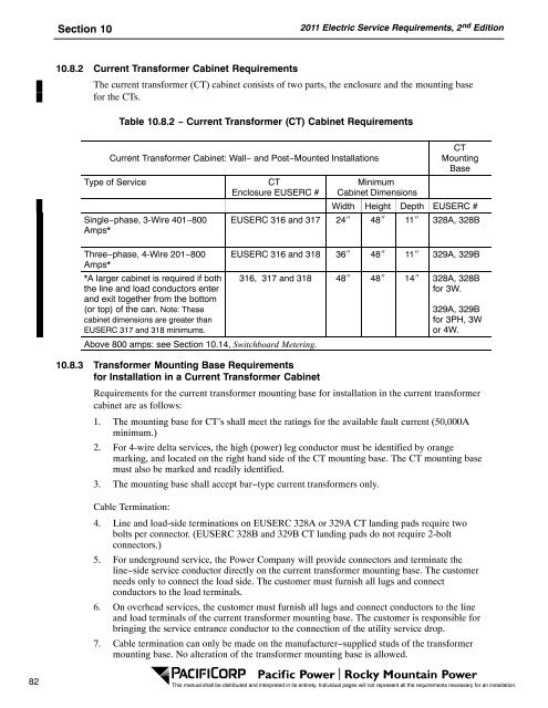
10.8.2 Current Transformer Cabinet <strong>Requirements</strong><br />
The current transformer (CT) cabinet consists of two parts, the enclosure and the mounting base<br />
for the CTs.<br />
Table 10.8.2 − Current Transformer (CT) Cabinet <strong>Requirements</strong><br />
Current Transformer Cabinet: Wall− and Post−Mounted Installations<br />
Type of <strong>Service</strong><br />
Single−phase, 3-Wire 401−800<br />
Amps*<br />
Three−phase, 4-Wire 201−800<br />
Amps*<br />
*A larger cabinet is required if both<br />
the line and load conductors enter<br />
and exit together from the bottom<br />
(or top) of the can. Note: These<br />
cabinet dimensions are greater than<br />
EUSERC 317 and 318 minimums.<br />
CT<br />
Enclosure EUSERC #<br />
Above 800 amps: see Section 10.14, Switchboard Metering.<br />
CT<br />
Mounting<br />
Base<br />
Minimum<br />
Cabinet Dimensions<br />
Width Height Depth EUSERC #<br />
EUSERC 316 and 317 24 48 11 328A, 328B<br />
EUSERC 316 and 318 36 48 11 329A, 329B<br />
316, 317 and 318 48 48 14 328A, 328B<br />
for 3W.<br />
329A, 329B<br />
for 3PH, 3W<br />
or 4W.<br />
10.8.3 Transformer Mounting Base <strong>Requirements</strong><br />
for Installation in a Current Transformer Cabinet<br />
<strong>Requirements</strong> for the current transformer mounting base for installation in the current transformer<br />
cabinet are as follows:<br />
1. The mounting base for CT’s shall meet the ratings for the available fault current (50,000A<br />
minimum.)<br />
2. For 4-wire delta services, the high (power) leg conductor must be identified by orange<br />
marking, and located on the right hand side of the CT mounting base. The CT mounting base<br />
must also be marked and readily identified.<br />
3. The mounting base shall accept bar−type current transformers only.<br />
Cable Termination:<br />
4. Line and load-side terminations on EUSERC 328A or 329A CT landing pads require two<br />
bolts per connector. (EUSERC 328B and 329B CT landing pads do not require 2-bolt<br />
connectors.)<br />
5. For underground service, the <strong>Power</strong> Company will provide connectors and terminate the<br />
line−side service conductor directly on the current transformer mounting base. The customer<br />
needs only to connect the load side. The customer must furnish all lugs and connect<br />
conductors to the load terminals.<br />
6. On overhead services, the customer must furnish all lugs and connect conductors to the line<br />
and load terminals of the current transformer mounting base. The customer is responsible for<br />
bringing the service entrance conductor to the connection of the utility service drop.<br />
7. Cable termination can only be made on the manufacturer−supplied studs of the transformer<br />
mounting base. No alteration of the transformer mounting base is allowed.<br />
82<br />
This manual shall be distributed and interpreted in its entirety. Individual pages will not represent all the requirements necessary for an installation.