Power Management Design Guide for Altera® FPGAs and CPLDs ...
Power Management Design Guide for Altera® FPGAs and CPLDs ...
Power Management Design Guide for Altera® FPGAs and CPLDs ...

You also want an ePaper? Increase the reach of your titles
YUMPU automatically turns print PDFs into web optimized ePapers that Google loves.
<strong>Design</strong> tools<br />
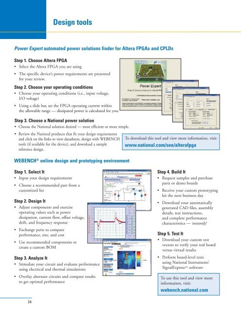
<strong>Power</strong> Expert automated power solutions finder <strong>for</strong> Altera <strong>FPGAs</strong> <strong>and</strong> <strong>CPLDs</strong><br />
Step 1. Choose Altera FPGA<br />
• Select the Altera FPGA you are using<br />
• The specific device’s power requirements are presented<br />
<strong>for</strong> your review.<br />
Step 2. Choose your operating conditions<br />
• Choose your operating conditions (i.e., input voltage,<br />
I/O voltage)<br />
• Using a slide bar, set the FPGA operating current within<br />
the allowable range — dissipated power is calculated <strong>for</strong> you.<br />
Step 3. Choose a National power solution<br />
• Choose the National solution desired — most efficient or more simple.<br />
• Review the National products that fit your design requirements<br />
<strong>and</strong> click on the links to view datasheets, design with WEBENCH<br />
tools (if available <strong>for</strong> the device), <strong>and</strong> download a sample<br />
reference design.<br />
To download this tool <strong>and</strong> view more in<strong>for</strong>mation, visit:<br />
www.national.com/see/alterafpga<br />
WEBENCH ® online design <strong>and</strong> prototyping environment<br />
Step 1. Select It<br />
• Input your design requirements<br />
• Choose a recommended part from a<br />
customized list<br />
Step 2. <strong>Design</strong> It<br />
• Adjust components <strong>and</strong> exercise<br />
operating values such as power<br />
dissipation, current flow, offset voltage,<br />
drift, <strong>and</strong> frequency response<br />
• Exchange parts to compare<br />
per<strong>for</strong>mance, size, <strong>and</strong> cost<br />
• Use recommended components or<br />
create a custom BOM<br />
Step 3. Analyze It<br />
• Stimulate your circuit <strong>and</strong> evaluate per<strong>for</strong>mance<br />
using electrical <strong>and</strong> thermal simulations<br />
• Overlay alternate circuits <strong>and</strong> compare results<br />
to get optimal per<strong>for</strong>mance<br />
Step 4. Build It<br />
• Request samples <strong>and</strong> purchase<br />
parts or demo boards<br />
• Receive your custom prototyping<br />
kit the next business day<br />
• Download your automatically<br />
generated CAD files, assembly<br />
details, test instructions,<br />
<strong>and</strong> complete per<strong>for</strong>mance<br />
characteristics — instantly!<br />
Step 5. Test It<br />
• Download your custom test<br />
vectors to verify your real board<br />
versus virtual results<br />
• Per<strong>for</strong>m board-level tests<br />
using National Instruments’<br />
SignalExpress software<br />
To use this tool <strong>and</strong> view more<br />
in<strong>for</strong>mation, visit:<br />
webench.national.com<br />
24