AIDJEX Bulletin #40 - Polar Science Center - University of Washington
AIDJEX Bulletin #40 - Polar Science Center - University of Washington
AIDJEX Bulletin #40 - Polar Science Center - University of Washington
Create successful ePaper yourself
Turn your PDF publications into a flip-book with our unique Google optimized e-Paper software.
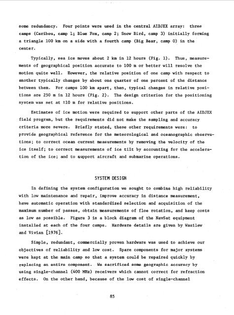
some redundancy. Four points were used in the central <strong>AIDJEX</strong> array: three<br />
camps (Caribou, camp 1; Blue Fox, camp 2; Snow Bird, camp 3) initially forming<br />
a triangle 100 km on a side with a fourth camp (Big Bear, camp 0) in the<br />
center.<br />
Typically, sea ice moves about 2 km in 12 hours (Fig. 1). Thus, measurements<br />
<strong>of</strong> geographical position accurate to 100 m or better will resolve the<br />
motion quite well. However, the relative position <strong>of</strong> one camp with respect to<br />
another typically changes by about one quarter <strong>of</strong> one percent <strong>of</strong> the distance<br />
between them. For camps 100 km apart, then, typical changes in relative positions<br />
are 250 m in 12 hours (Fig. 2). The design criterion for the positioning<br />
system was set at 510 m for relative positions.<br />
Estimates <strong>of</strong> ice motion were required to support other parts <strong>of</strong> the <strong>AIDJEX</strong><br />
field program, but the requirements did not make the sampling and accuracy<br />
criteria more severe. Briefly stated, these other requirements were: to<br />
provide geographical reference for the meteorological and oceanographic observations;<br />
to correct ocean current measurements by removing the velocity <strong>of</strong> the<br />
ice itself; to correct measurements <strong>of</strong> ice tilt by accounting for the acceleration<br />
<strong>of</strong> the ice; and to support aircraft and submarine operations.<br />
SYSTEM DESIGN<br />
In defining the system configuration we sought to combine high reliability<br />
with low maintenance and repair, improve accuracy in distance measurement,<br />
have automatic operation with standardized selection and acquisition <strong>of</strong> the<br />
maximum number <strong>of</strong> passes, obtain measurements <strong>of</strong> floe rotation, and keep costs<br />
as low as possible. Figure 3 is a block diagram <strong>of</strong> the NavSat equipment<br />
installed at each <strong>of</strong> the four camps. Hardware details are given by Wasilew<br />
and Vivian [1976].<br />
Simple, redundant, commercially proven hardware was used to achieve our<br />
objectives <strong>of</strong> reliability and low cost. Spare components for major systems<br />
were kept at the main camp so that a system could be repaired quickly by<br />
replacing an entire component. We sacrificed some geographic accuracy by<br />
using single-channel (400 MHz) receivers which cannot correct for refraction<br />
effects. On the other hand, because <strong>of</strong> the low cost <strong>of</strong> single-channel<br />
85


