Responder LE Model 5701 Security and Remote Start Installation ...
Responder LE Model 5701 Security and Remote Start Installation ...
Responder LE Model 5701 Security and Remote Start Installation ...

You also want an ePaper? Increase the reach of your titles
YUMPU automatically turns print PDFs into web optimized ePapers that Google loves.
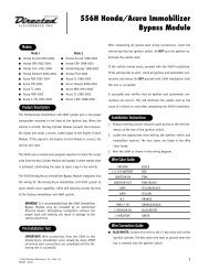
<strong>Responder</strong> <strong>LE</strong> Quick Reference Wiring Guide<br />
D2D jumpers: must be horizontal<br />
For connecting to external modules<br />
for use with external module.<br />
Antenna four-pin connector<br />
Red/White aux trunk release (-) 200mA<br />
Red 12v (+) constant input<br />
Brown siren (+) output<br />
White/Brown Flex parking light relay 87A<br />
Black chassis ground<br />
Violet door (+) input<br />
Blue trunk (-) instant trigger input<br />
Greendoor (-) input<br />
Black/white domelight 200mA (-) output<br />
White/Blue remote start activation(-) input<br />
White parking light output 30<br />
Orange ground-when-armed (-) 500mA output<br />
IMPORTANT!<br />
Neutral safety must be plugged in<br />
<strong>and</strong> in the On position.<br />
ON<br />
D2D<br />
Data-to-data<br />
connector<br />
Black/White neutral safety (-) input<br />
Violet/White tach input<br />
Brown brake shut down (+) input<br />
H1<br />
Bitwriter<br />
ESP<br />
Tach<br />
Threshold<br />
Jumper<br />
Hi Lo<br />
Neutral Safety<br />
Switch<br />
RS in<br />
Access Door<br />
Light Flash Fuse Jumper<br />
under door. Use needlenose<br />
pliers to change fuse<br />
position.<br />
Door<br />
Lock/unlock<br />
Status <strong>LE</strong>D Output (use White two-pin from antenna cable)<br />
Valet Program switch input (use Blue two-pin from antenna cable)<br />
Blue RS status (-) 200mA output<br />
Pink RS ignition1 (-) 200mA output<br />
Violet RS starter (-) 200mA output<br />
Orange RS accessory (-) 200mA output<br />
Pink ignition 1 (+) output (also ignition sense input)<br />
Red/white fused 30a (contact 87 of RS Flex Relay)<br />
Orange accessory output<br />
Violet starter output (car side of starter wire)<br />
Green starter input (key side of starter wire)<br />
Red 12V(+) constant fused 30a input (for Ignition1 relay)<br />
Pink/ White Flex Relay output (default is ignition 2)<br />
Pink/black Flex Relay contact 87a (default is ignition 2)<br />
Red/black fused 30a( for accessory <strong>and</strong> starter relays)<br />
<strong>Remote</strong> start output Optional Mux sensor port<br />
H2 Relay out<br />
H3<br />
Pink/ White flex (-) 200mA output (default setting is ignition 2)<br />
Note: Wires 1 - 4 on the auxiliary outputs are wired to the (-) triggers for<br />
the onboard remote start relays <strong>and</strong> are not diode isolated. If wiring directly<br />
to the vehicle place a 1-amp diode in line to prevent feedback from the vehicle.<br />
Green<br />
Blue<br />
(-) Lock<br />
(+) Unlock<br />
Gray hood pin switch NO/NC (-) input<br />
(-) Unlock<br />
(+) Lock<br />
Blue/White<br />
2nd remote start status (-) 200mA output<br />
Defogger (programmable)<br />
Heavy gauge 10-pin connection rear view<br />
N/C<br />
RED/BLACK<br />
PINK/BLACK<br />
PINK/WHITE<br />
RED<br />
Light Green/ Black OEM disarm (-) 200mA output<br />
Light Green/ White OEM arm (-) 200mA output<br />
10 9 8 7 6<br />
White/ Violet AUX 1 (-) 200mA output<br />
PINK<br />
RED/WHITE<br />
Violet/Black AUX 2 (-) 200mA output<br />
ORANGE<br />
White/ Black AUX 3(-) 200mA output<br />
VIO<strong>LE</strong>T<br />
Light Blue 2nd Unlock (-) 200mA output<br />
GREEN<br />
Gray/ Black wait-to-start (-) input<br />
Brown/Black (-) 200mA Horn honk output<br />
© 2008 Directed Electronics<br />
5<br />
4<br />
3<br />
2<br />
1<br />
© 2008 Directed Electronics—all rights reserved 89