Installation and Operating Instructions - Crompton Instruments
Installation and Operating Instructions - Crompton Instruments
Installation and Operating Instructions - Crompton Instruments

Create successful ePaper yourself
Turn your PDF publications into a flip-book with our unique Google optimized e-Paper software.
Testing Relay 1<br />
Now you are ready to test the relay<br />
contact function. This example assumes<br />
a nominal 120V product.<br />
With no measuring signal input, the relay<br />
should be tripped (no Voltage ). Confirm<br />
that Relay 1 contact is de-energised.<br />
Apply a three-phase, variable, AC voltage<br />
source to the input, initially set to 120V.<br />
Now decrease the voltage slowly.<br />
Confirm Relay 1 contact is energised.<br />
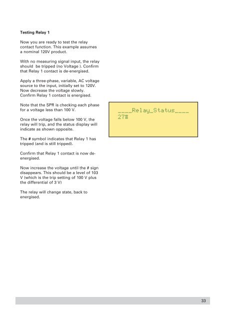
Note that the SPR is checking each phase<br />
for a voltage less than 100 V.<br />
Once the voltage falls below 100 V, the<br />
relay will trip, <strong>and</strong> the status display will<br />
indicate as shown opposite.<br />
The # symbol indicates that Relay 1 has<br />
tripped (<strong>and</strong> is still tripped).<br />
Confirm that Relay 1 contact is now deenergised.<br />
Now increase the voltage until the # sign<br />
disappears. This should be a level of 103<br />
V (which is the trip setting of 100 V plus<br />
the differential of 3 V)<br />
The relay will change state, back to<br />
energised.<br />
33