Installation and Operating Instructions - Crompton Instruments
Installation and Operating Instructions - Crompton Instruments
Installation and Operating Instructions - Crompton Instruments

You also want an ePaper? Increase the reach of your titles
YUMPU automatically turns print PDFs into web optimized ePapers that Google loves.
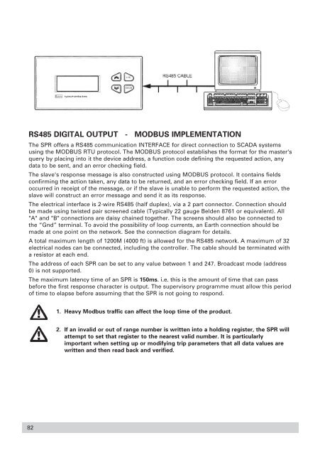
RS485 DIGITAL OUTPUT - MODBUS IMPLEMENTATION<br />
The SPR offers a RS485 communication INTERFACE for direct connection to SCADA systems<br />
using the MODBUS RTU protocol. The MODBUS protocol establishes the format for the master's<br />
query by placing into it the device address, a function code defining the requested action, any<br />
data to be sent, <strong>and</strong> an error checking field.<br />
The slave's response message is also constructed using MODBUS protocol. It contains fields<br />
confirming the action taken, any data to be returned, <strong>and</strong> an error checking field. If an error<br />
occurred in receipt of the message, or if the slave is unable to perform the requested action, the<br />
slave will construct an error message <strong>and</strong> send it as its response.<br />
The electrical interface is 2-wire RS485 (half duplex), via a 2 part connector. Connection should<br />
be made using twisted pair screened cable (Typically 22 gauge Belden 8761 or equivalent). All<br />
"A" <strong>and</strong> "B" connections are daisy chained together. The screens should also be connected to<br />
the “Gnd” terminal. To avoid the possibility of loop currents, an Earth connection should be<br />
made at one point on the network. See the connection diagram for details.<br />
A total maximum length of 1200M (4000 ft) is allowed for the RS485 network. A maximum of 32<br />
electrical nodes can be connected, including the controller. The cable should be terminated with<br />
a resistor at each end.<br />
The address of each SPR can be set to any value between 1 <strong>and</strong> 247. Broadcast mode (address<br />
0) is not supported.<br />
The maximum latency time of an SPR is 150ms. i.e. this is the amount of time that can pass<br />
before the first response character is output. The supervisory programme must allow this period<br />
of time to elapse before assuming that the SPR is not going to respond.<br />
1. Heavy Modbus traffic can affect the loop time of the product.<br />
2. If an invalid or out of range number is written into a holding register, the SPR will<br />
attempt to set that register to the nearest valid number. It is particularly<br />
important when setting up or modifying trip parameters that all data values are<br />
written <strong>and</strong> then read back <strong>and</strong> verified.<br />
82