Hardware Interface Description - Wireless Data Modules
Hardware Interface Description - Wireless Data Modules
Hardware Interface Description - Wireless Data Modules

You also want an ePaper? Increase the reach of your titles
YUMPU automatically turns print PDFs into web optimized ePapers that Google loves.
MC55/56 <strong>Hardware</strong> <strong>Interface</strong> <strong>Description</strong><br />
Confidential / Released<br />
s<br />
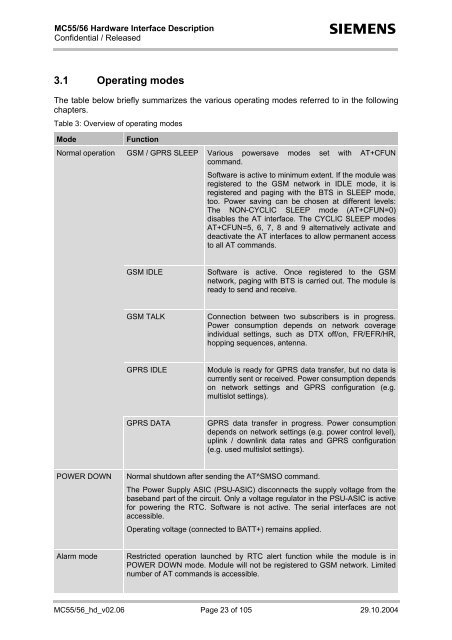
3.1 Operating modes<br />
The table below briefly summarizes the various operating modes referred to in the following<br />
chapters.<br />
Table 3: Overview of operating modes<br />
Mode<br />
Normal operation<br />
Function<br />
GSM / GPRS SLEEP Various powersave modes set with AT+CFUN<br />
command.<br />
Software is active to minimum extent. If the module was<br />
registered to the GSM network in IDLE mode, it is<br />
registered and paging with the BTS in SLEEP mode,<br />
too. Power saving can be chosen at different levels:<br />
The NON-CYCLIC SLEEP mode (AT+CFUN=0)<br />
disables the AT interface. The CYCLIC SLEEP modes<br />
AT+CFUN=5, 6, 7, 8 and 9 alternatively activate and<br />
deactivate the AT interfaces to allow permanent access<br />
to all AT commands.<br />
GSM IDLE<br />
Software is active. Once registered to the GSM<br />
network, paging with BTS is carried out. The module is<br />
ready to send and receive.<br />
GSM TALK<br />
Connection between two subscribers is in progress.<br />
Power consumption depends on network coverage<br />
individual settings, such as DTX off/on, FR/EFR/HR,<br />
hopping sequences, antenna.<br />
GPRS IDLE<br />
Module is ready for GPRS data transfer, but no data is<br />
currently sent or received. Power consumption depends<br />
on network settings and GPRS configuration (e.g.<br />
multislot settings).<br />
GPRS DATA<br />
GPRS data transfer in progress. Power consumption<br />
depends on network settings (e.g. power control level),<br />
uplink / downlink data rates and GPRS configuration<br />
(e.g. used multislot settings).<br />
POWER DOWN<br />
Normal shutdown after sending the AT^SMSO command.<br />
The Power Supply ASIC (PSU-ASIC) disconnects the supply voltage from the<br />
baseband part of the circuit. Only a voltage regulator in the PSU-ASIC is active<br />
for powering the RTC. Software is not active. The serial interfaces are not<br />
accessible.<br />
Operating voltage (connected to BATT+) remains applied.<br />
Alarm mode<br />
Restricted operation launched by RTC alert function while the module is in<br />
POWER DOWN mode. Module will not be registered to GSM network. Limited<br />
number of AT commands is accessible.<br />
MC55/56_hd_v02.06 Page 23 of 105 29.10.2004