Hardware Interface Description - Wireless Data Modules
Hardware Interface Description - Wireless Data Modules
Hardware Interface Description - Wireless Data Modules
You also want an ePaper? Increase the reach of your titles
YUMPU automatically turns print PDFs into web optimized ePapers that Google loves.
MC55/56 <strong>Hardware</strong> <strong>Interface</strong> <strong>Description</strong><br />
Confidential / Released<br />
s<br />
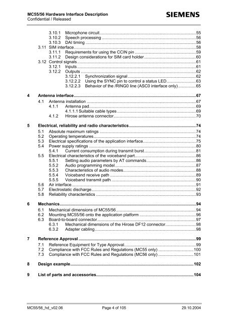
3.10.1 Microphone circuit..................................................................................55<br />
3.10.2 Speech processing ................................................................................56<br />
3.10.3 DAI timing ..............................................................................................56<br />
3.11 SIM interface........................................................................................................58<br />
3.11.1 Requirements for using the CCIN pin ....................................................59<br />
3.11.2 Design considerations for SIM card holder............................................60<br />
3.12 Control signals .....................................................................................................61<br />
3.12.1 Inputs .....................................................................................................61<br />
3.12.2 Outputs ..................................................................................................62<br />
3.12.2.1 Synchronization signal..........................................................62<br />
3.12.2.2 Using the SYNC pin to control a status LED.........................63<br />
3.12.2.3 Behavior of the /RING0 line (ASC0 interface only) ...............65<br />
4 Antenna interface........................................................................................................67<br />
4.1 Antenna installation .............................................................................................67<br />
4.1.1 Antenna pad...........................................................................................69<br />
4.1.1.1 Suitable cable types ...................................................................69<br />
4.1.2 Hirose antenna connector......................................................................70<br />
5 Electrical, reliability and radio characteristics.........................................................74<br />
5.1 Absolute maximum ratings ..................................................................................74<br />
5.2 Operating temperatures.......................................................................................74<br />
5.3 Electrical specifications of the application interface.............................................75<br />
5.4 Power supply ratings ...........................................................................................80<br />
5.4.1 Current consumption during transmit burst............................................81<br />
5.5 Electrical characteristics of the voiceband part....................................................86<br />
5.5.1 Setting audio parameters by AT commands..........................................86<br />
5.5.2 Audio programming model.....................................................................87<br />
5.5.3 Characteristics of audio modes..............................................................88<br />
5.5.4 Voiceband receive path .........................................................................89<br />
5.5.5 Voiceband transmit path ........................................................................90<br />
5.6 Air interface..........................................................................................................91<br />
5.7 Electrostatic discharge.........................................................................................92<br />
5.8 Reliability characteristics .....................................................................................93<br />
6 Mechanics....................................................................................................................94<br />
6.1 Mechanical dimensions of MC55/56....................................................................94<br />
6.2 Mounting MC55/56 onto the application platform ................................................96<br />
6.3 Board-to-board connector....................................................................................97<br />
6.3.1 Mechanical dimensions of the Hirose DF12 connector..........................98<br />
6.3.2 Adapter cabling......................................................................................98<br />
7 Reference Approval ....................................................................................................99<br />
7.1 Reference Equipment for Type Approval.............................................................99<br />
7.2 Compliance with FCC Rules and Regulations (MC55 only) ..............................100<br />
7.3 Compliance with FCC Rules and Regulations (MC56 only) ..............................101<br />
8 Design example.........................................................................................................102<br />
9 List of parts and accessories...................................................................................104<br />
MC55/56_hd_v02.06 Page 4 of 105 29.10.2004


