Hardware Interface Description - Wireless Data Modules
Hardware Interface Description - Wireless Data Modules
Hardware Interface Description - Wireless Data Modules

You also want an ePaper? Increase the reach of your titles
YUMPU automatically turns print PDFs into web optimized ePapers that Google loves.
MC55/56 <strong>Hardware</strong> <strong>Interface</strong> <strong>Description</strong><br />
Confidential / Released<br />
s<br />
3.2 Power supply<br />
The power supply of MC55/56 has to be a single voltage source of V BATT += 3.3V...4.8V. It<br />
must be able to provide sufficient current in a transmit burst which typically rises to 2A.<br />
Beyond that, the power supply must be able to account for increased current consumption if<br />
the module is exposed to inappropriate conditions, for example antenna mismatch. For<br />
further details see Chapters 3.2.2 and 5.4.1.<br />
All the key functions for supplying power to the device are handled by an ASIC power supply.<br />
The ASIC provides the following features:<br />
• Stabilizes the supply voltages for the GSM baseband using low drop linear voltage<br />
regulators.<br />
• Controls the module's power up and power down procedures.<br />
A watchdog logic implemented in the baseband processor periodically sends signals to<br />
the ASIC, allowing it to maintain the supply voltage for all digital MC55/56 components.<br />
Whenever the watchdog pulses fail to arrive constantly, the module is turned off.<br />
• Delivers, across the VDD pin, a regulated voltage of 2.9V. The output voltage VDD may<br />
be used to supply, for example, an external LED or a level shifter. However, the external<br />
circuitry must not cause any spikes or glitches on voltage VDD. This voltage is not<br />
available in POWER DOWN mode. Therefore, the VDD pin can be used to indicate<br />
whether or not MC55/56 is in POWER DOWN mode.<br />
• Provides power to the SIM interface.<br />
The RF power amplifier is driven directly from BATT+.<br />
3.2.1 Power supply pins on the board-to-board connector<br />
Five BATT+ pins of the board-to-board connector are dedicated to connect the supply<br />
voltage, five GND pins are recommended for grounding. The values stated below must be<br />
measured directly at the reference points on the MC55/56 board (TP BATT+ and TP GND<br />
illustrated in Figure 40).<br />
The POWER and CHARGE pins serve as control signals for charging a Li-Ion battery.<br />
VDDLP can be used to back up the RTC.<br />
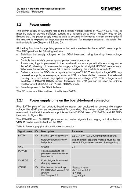
Table 4: Power supply pins of board-to-board connector<br />
Signal name I/O <strong>Description</strong> Parameter<br />
BATT+ I/O Positive operating voltage<br />
Reference points are the<br />
test points<br />
GND - Ground 0 V<br />
POWER I This line signals to the<br />
processor that the charger<br />
is connected.<br />
CHARGE O Control signal for external<br />
charging transistor<br />
VDDLP I/O Can be used to back up<br />
the RTC when V BATT+ is not<br />
applied.<br />
See Chapter 3.8<br />
3.3 V...4.8 V, I typ ≤ 2 A during transmit burst<br />
The minimum operating voltage must not fall<br />
below 3.3 V, not even in case of voltage drop.<br />
U OUT,max < V BATT+<br />
U IN = 2.0 V...5.5 V<br />
R i = 1kΩ<br />
I in,max = 30µA<br />
MC55/56_hd_v02.06 Page 25 of 105 29.10.2004