Hardware Interface Description - Wireless Data Modules
Hardware Interface Description - Wireless Data Modules
Hardware Interface Description - Wireless Data Modules
Create successful ePaper yourself
Turn your PDF publications into a flip-book with our unique Google optimized e-Paper software.
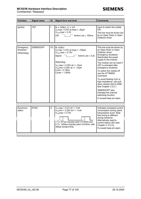
MC55/56 <strong>Hardware</strong> <strong>Interface</strong> <strong>Description</strong><br />
Confidential / Released<br />
s<br />
Function Signal name IO Signal form and level Comments<br />
Ignition /IGT I R I ≈ 100kΩ, C I ≈ 1nF<br />
V IL max = 0.5V at Imax = -20µA<br />
V Open max = 2.3V<br />
ON<br />
~~~ |____| ~~~ Active Low ≥ 100ms<br />
Input to switch the mobile<br />
ON.<br />
The line must be driven low<br />
by an Open Drain or Open<br />
Collector driver.<br />
Emergency<br />
shutdown<br />
(Watchdog)<br />
/EMERGOFF I/O R I ≈22kΩ<br />
V IL max = 0.5V at Imax = -100µA<br />
V Open max = 2.73V<br />
Signal<br />
~~~ |______| ~~~ Active Low ≥ 3.2s<br />
Watchdog:<br />
V OL max = 0.35V at I = 10µA<br />
V OH min= 2.25V at I = -10µA<br />
f O min = 0.16Hz<br />
f O max = 1.55Hz<br />
This line must be driven by<br />
an Open Drain or Open<br />
Collector driver.<br />
Emergency shutdown<br />
deactivates the power<br />
supply to the module.<br />
The module can be reset if<br />
/IGT is activated after<br />
emergency shutdown.<br />
To switch the mobile off<br />
use the AT^SMSO<br />
command.<br />
To avoid floating if pin is<br />
high impedance, use pulldown<br />
resistor tied to GND.<br />
See Chapter 3.3.2.1.<br />
/EMERGOFF also<br />
indicates the internal<br />
watchdog function.<br />
If unused keep pin open.<br />
Synchronization<br />
SYNC<br />
O<br />
V OL max = 0.2V at I = 1mA<br />
V OH min = 2.35V at I = -1mA<br />
V OH max = 2.73V<br />
1 Tx, 877µs impulse each 4.616ms and<br />
2 Tx, 1454µs impulse each 4.616ms, with<br />
300µs forward time.<br />
Indicates increased current<br />
consumption during uplink<br />
transmission burst. Note<br />
that timing is different<br />
during handover.<br />
Alternatively used to<br />
control status LED (see<br />
Chapter 3.12.2.2).<br />
If unused keep pin open.<br />
MC55/56_hd_v02.06 Page 77 of 105 29.10.2004


