Hardware Interface Description - Wireless Data Modules
Hardware Interface Description - Wireless Data Modules
Hardware Interface Description - Wireless Data Modules

Create successful ePaper yourself
Turn your PDF publications into a flip-book with our unique Google optimized e-Paper software.
MC55/56 <strong>Hardware</strong> <strong>Interface</strong> <strong>Description</strong><br />
Confidential / Released<br />
s<br />
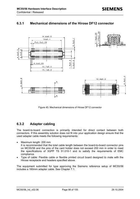
6.3.1 Mechanical dimensions of the Hirose DF12 connector<br />
Figure 45: Mechanical dimensions of Hirose DF12 connector<br />
6.3.2 Adapter cabling<br />
The board-to-board connection is primarily intended for direct contact between both<br />
connectors. If this assembly solution does not fit into your application design ensure that the<br />
used adapter cable meets the following requirements:<br />
• Maximum length: 200 mm<br />
It is recommended that the total cable length between the board-to-board connector pins<br />
on MC55/56 and the pins of the card holder does not exceed 200 mm in order to meet<br />
the specifications of 3GPP TS 51.010-1 and to satisfy the requirements of EMC<br />
compliance.<br />
• Type of cable: Flexible cable or flexible printed circuit board designed to mate with the<br />
Hirose receptacle and headers specified above.<br />
The equipment submitted for type approving the Siemens reference setup of MC55/56<br />
includes a 160mm adapter cable. See Chapter 7.1.<br />
MC55/56_hd_v02.06 Page 98 of 105 29.10.2004