Hardware Interface Description - Wireless Data Modules
Hardware Interface Description - Wireless Data Modules
Hardware Interface Description - Wireless Data Modules
You also want an ePaper? Increase the reach of your titles
YUMPU automatically turns print PDFs into web optimized ePapers that Google loves.
MC55/56 <strong>Hardware</strong> <strong>Interface</strong> <strong>Description</strong><br />
Confidential / Released<br />
s<br />
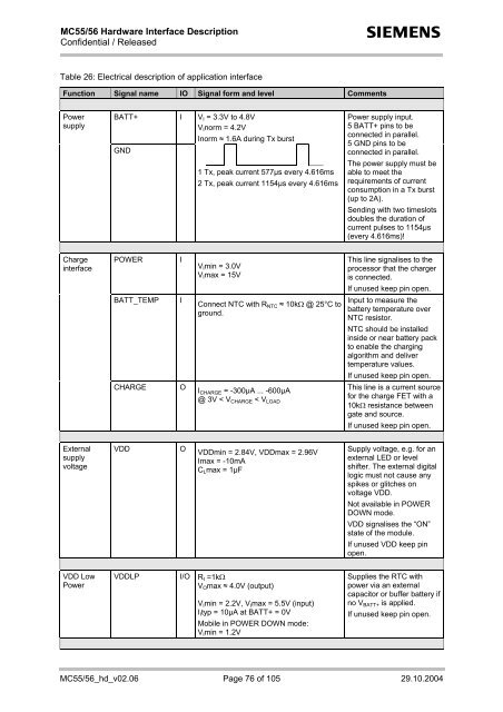
Table 26: Electrical description of application interface<br />
Function Signal name IO Signal form and level Comments<br />
Power<br />
supply<br />
BATT+ I V I = 3.3V to 4.8V<br />
V I norm = 4.2V<br />
Inorm ≈ 1.6A during Tx burst<br />
GND<br />
1 Tx, peak current 577µs every 4.616ms<br />
2 Tx, peak current 1154µs every 4.616ms<br />
Power supply input.<br />
5 BATT+ pins to be<br />
connected in parallel.<br />
5 GND pins to be<br />
connected in parallel.<br />
The power supply must be<br />
able to meet the<br />
requirements of current<br />
consumption in a Tx burst<br />
(up to 2A).<br />
Sending with two timeslots<br />
doubles the duration of<br />
current pulses to 1154µs<br />
(every 4.616ms)!<br />
Charge<br />
interface<br />
POWER<br />
I<br />
V I min = 3.0V<br />
V I max = 15V<br />
This line signalises to the<br />
processor that the charger<br />
is connected.<br />
If unused keep pin open.<br />
BATT_TEMP<br />
I<br />
Connect NTC with R NTC ≈ 10kΩ @ 25°C to<br />
ground.<br />
Input to measure the<br />
battery temperature over<br />
NTC resistor.<br />
NTC should be installed<br />
inside or near battery pack<br />
to enable the charging<br />
algorithm and deliver<br />
temperature values.<br />
If unused keep pin open.<br />
CHARGE<br />
O<br />
I CHARGE = -300µA ... -600µA<br />
@ 3V < V CHARGE < V LOAD<br />
This line is a current source<br />
for the charge FET with a<br />
10kΩ resistance between<br />
gate and source.<br />
If unused keep pin open.<br />
External<br />
supply<br />
voltage<br />
VDD<br />
O<br />
VDDmin = 2.84V, VDDmax = 2.96V<br />
Imax = -10mA<br />
C L max = 1µF<br />
Supply voltage, e.g. for an<br />
external LED or level<br />
shifter. The external digital<br />
logic must not cause any<br />
spikes or glitches on<br />
voltage VDD.<br />
Not available in POWER<br />
DOWN mode.<br />
VDD signalises the “ON”<br />
state of the module.<br />
If unused VDD keep pin<br />
open.<br />
VDD Low<br />
Power<br />
VDDLP I/O R I =1kΩ<br />
V O max ≈ 4.0V (output)<br />
V I min = 2.2V, V I max = 5.5V (input)<br />
I I typ = 10µA at BATT+ = 0V<br />
Mobile in POWER DOWN mode:<br />
V I min = 1.2V<br />
Supplies the RTC with<br />
power via an external<br />
capacitor or buffer battery if<br />
no V BATT+ is applied.<br />
If unused keep pin open.<br />
MC55/56_hd_v02.06 Page 76 of 105 29.10.2004


